Posts Tagged ‘raspberry pi’
Which Assembly Language Book is Right for You
Introduction
I’ve now written four books on Assembly Language programming, three for ARM processors and now one for RISC-V processors. This article explains why there are three books for ARM CPUs and then where people will find RISC-V CPUs.
The Three Instruction Sets for ARM CPUs
The ARM processor started development in 1983 as a 16-bit replacement for the popular 8-bit 6502 used in many popular personal computers such as the Apple II and Commodore PET. This CPU was used in the Acorn computer, mostly sold in the UK. I haven’t written a book on 16-bit ARM Assembly Language, as it is pretty much non-existent in today’s world.
32-Bit ARM
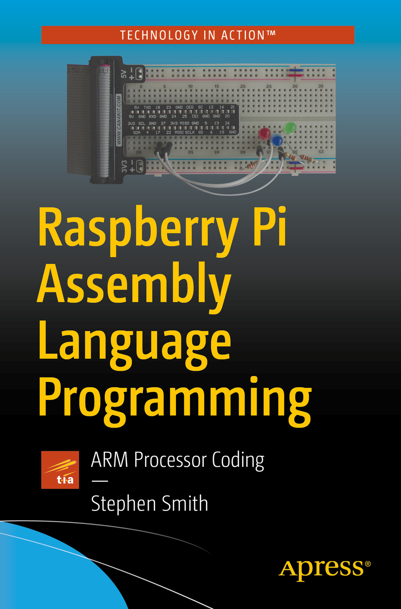
The ARM processor became popular when the 32-bit version was released and Apple chose it as the CPU for the iPod music player. From this start, the ARM processor took over the mobile world being used in most mobile devices. When I wrote “Raspberry Pi Assembly Language Programming”, the Raspberry Pi OS was still a 32-bit operating system, although the CPU in the Raspberry Pi 3 and above was capable of 64-bits. Hence this book is really about 32-bit ARM Assembly Language Programming. Although it does have a chapter on 64-bit Assembly Language, since you could run 64-bit operating systems such as Kali Linux at the time.
64-Bit ARM
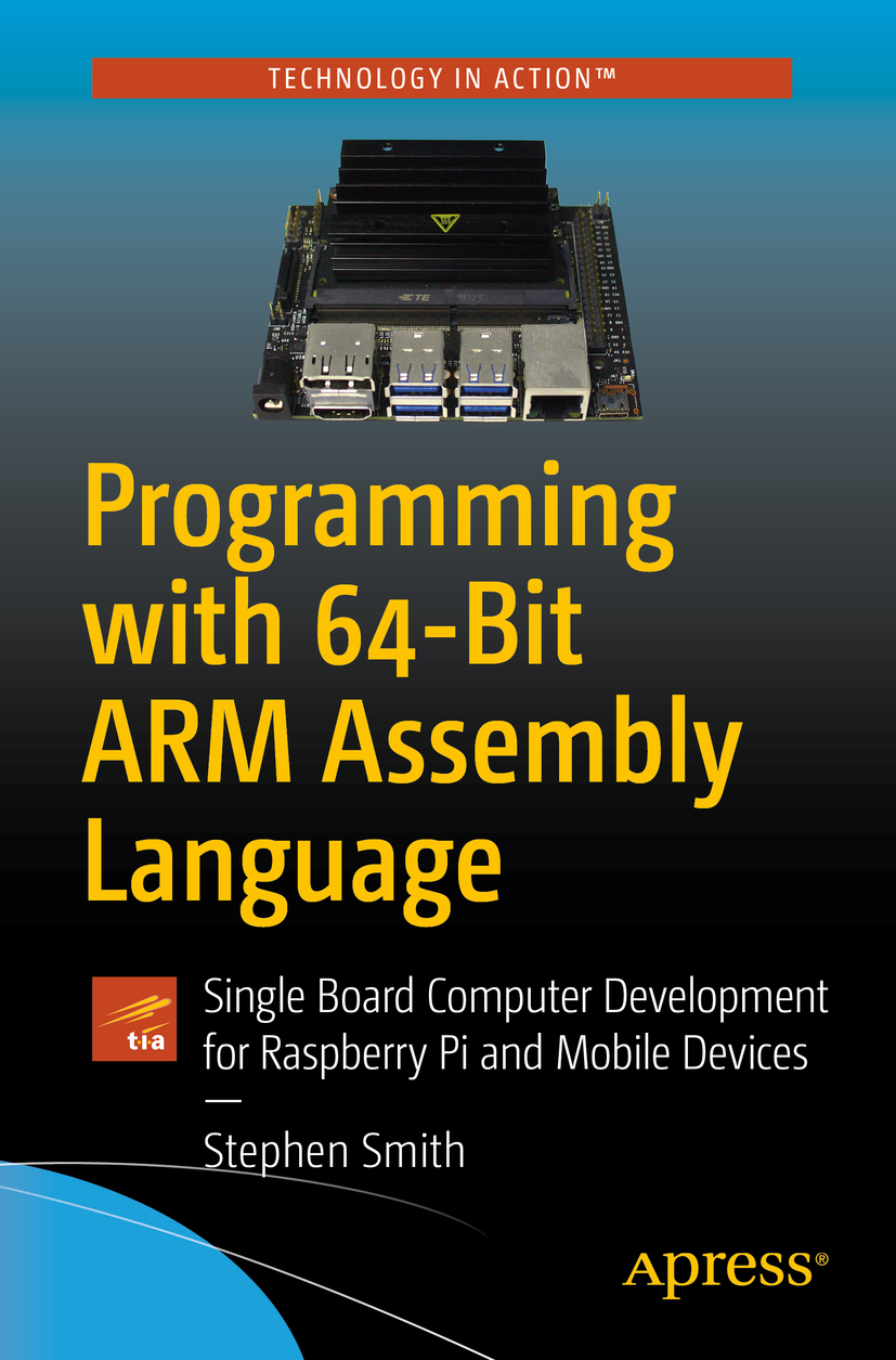
After finishing the 32-bit book, I felt a need to write a full 64-bit book. After all, iOS and Android had gone full ARM 64-bit for phones and tablets. Although the Raspberry Pi OS was still 32-bit, the popularity of 64-bit flavors of Linux was growing. The Raspberry Pi 4 finally had enough memory to run 64-bits well when it came out with 4Gig of RAM. So that led to my second book “Programming with 64-Bit ARM Assembly Language” which covers iOS, Android and Raspberry Pi 64-bit ARM Assembly Language Programming.
ARM learned a lot from its experience in the 32-bit world and as a consequence made the 64-bit instruction set quite different than the 32-bit one, addressing a lot of deficiencies and incorporating things that made compilers and performance much better.
Today even the Raspberry Pi OS has finally gone to a full 64-bits, though Raspberry still releases a 32-bit version as well.
32-Bit Thumbs its Nose
ARM holdings tries to make the ARM processor available in all CPU markets. The CPUs used in phones, tablets and Raspberry Pis are fairly high end. ARM also competes in the lower end microcontroller market. These devices are all 32-bit. However, these typically do not run the full 32-bit instruction set, but instead run a reduced version called the Thumb instruction set.
In 2021, Raspberry released their first microcontroller product, the Raspberry Pi Pico. With this they developed their own ARM based microcontroller, the RP2040. This led to my third book “RP2040 Assembly Language Programming”. This covers how to program ARM based microcontrollers in Assembly Language. Raspberry also sells its RP2040 chip to other companies and as a result there are a plethora of RP2040 base microcontrollers on the market today.

RISC-V
Intel/AMD processors dominate the desktop/laptop market and ARM dominates the mobile market. However, both these processors are proprietary and to use their instruction sets requires expensive licensing fees. Enter the RISC-V instruction set, created by professors at Berkeley University, as an open source instruction set that anyone can use free of any licensing fees. Note, that only the ISA is open source, the various hardware implementations of the ISA could be either proprietary or open source.
RISC-V is doing well in the microcontroller market where chips usually cost less than a dollar and built-in licensing fees can make chips uncompetitive. We’re beginning to see RISC-V based SBCs and laptops, although these are all quite low end at this point. I think RISC-V has a good future and with several RISC-V devices on the market to play with, I wrote “RISC-V Assembly Language Programming”.
In the case of ARM, the 32-bit and 64-bit instruction sets are quite different and two books were required. In the case of RISC-V both instruction sets are nearly identical with the main difference being the size of the registers. As a result I cover both 32-bit and 64-bit RISC-V Assembly Language in this one book.

Summary
This was a quick summary of why I’ve written four books on Assembly Language programming. Three for the various flavors of the ARM processor and my new one covering the new RISC-V CPUs.
How to Program a SunFounder PiDog
Introduction
Last time, the SunFounder PiDog was introduced, this time we’ll introduce how to program the PiDog to do our bidding. Previously, we looked at the SunFounder PiCar and how to program it. Both robots share the same RobotHat to interface the Raspberry Pi with the various servos, motors and devices attached to the robot. For the PiCar this is fairly simple as you just need to turn on the motors to go and set the steering servo to the angle you want to turn. The PiDog is much more complicated. There are eight servo motors that control the legs. On each leg, one servo sets the angle of the shoulder joint and the other sets the angle of the elbow joint. To get the PiDog to walk takes coordinating the setting of each of these servos in a coordinated fashion. SunFounder provides a PiDog Python class that hides most of the complexity, though it does give you direct access if you want to control the legs directly.

Introduction to the PiDog Class
To use the PiDog class, you need to instantiate a PiDog object and then start issuing commands. A common initialization sequence is:
       dog = Pidog()
       dog.do_action('stand', speed=80)
       dog.wait_all_done()
The first line creates a PiDog object to use, then the next line calls the do_action method which has a long list of standard actions. In the case of ‘stand’, it will set the eight leg servo motors to put the PiDog in the standing position. This is much easier than having to set all eight servo positions ourselves. Then you need to wait for this operation to complete before issuing another command, which is accomplished by calling the wait_all_done method.
The PiDog class uses multithreading so you can issue head and leg related commands at the same time and they are performed on separate threads. The head is reasonably complex as the neck consists of three servo motors. Similarly for the tail which is controlled by one servo motor. So you could start leg, head and tail commands before calling wait_all_done. Then you are free to issue another set of commands. If you issue a new command while a previous one is executing then the library will throw an exception.
To get the PiDog to move we use commands like the following actions:
       dog.do_action('trot', step_count=5, speed=98)
       dog.do_action('turn_right', step_count=5, speed=98)
       dog.do_action('backward', step_count=5, speed=98)
There are also apis to use the speaker, read the ultrasonic distance sensor and set the front LED strip such as:
   dog.speak("single_bark_1")
   dog.ultrasonic.read_distance()
   dog.rgb_strip.set_mode('breath', 'white', bps=0.5)
To use the camera, it is exactly the same as for the PiCar using the vilib library, as this is the same camera as the PiCar, connected in the same manner. The sample program below uses the vilib program to compare successive images to see if the PiDog is stuck, though this doesn’t work very well as the legs cause so much movement that the images are rarely the same.
Sample Program
I took the PiCar Roomba program and modified it to work with the PiDog. It doesn’t work as well as a Roomba, as the PiDog is quite a bit slower than the PiCar and the standard actions to turn the PiDog have quite a large turning radius. It might be nice if there were some standard actions to perhaps turn 180 degrees in a more efficient manner. The listing is at the end of the article.
Documentation
At the lowest level, all the source code for the Python classes like PiDog.py are included which are quite interesting to browse. Then there is a set of sample programs. The standard set is documented on the website, then there is a further set in a test folder that is installed, but not mentioned on the website. The website then has an easy coding section that explains the various parts of the PiDog class. Although there isn’t a reference document, I found the provided docs quite good and the source code easy enough to read for the complete picture.
Summary
Although coordinating eight servo motors to control walking is quite complicated, the PiDog class allows you to still control basic operations without having to understand that complexity. If you did want to program more complicated motion, like perhaps getting the PiDog to gallop then you are free to do so. I found programming the PiDog fairly straightforward and enjoyable. I find the way the PiDog moves quite interesting and this might give you a first look at more complicated robotic programming like you might encounter with a robot arm with a fully articulated hand.
from pidog import Pidog
import time
import random
from vilib import Vilib
import os
import cv2
import numpy as np
SPIRAL = 1
BACKANDFORTH = 2
STUCK = 3
state = SPIRAL
StartTurn = 80
foundObstacle = 40
StuckDist = 10
lastPhoto = ""
currentPhoto = ""
MSE_THRESHOLD = 20
def compareImages():
    if lastPhoto == "":
        return 0
    img1 = cv2.imread(lastPhoto)
    img2 = cv2.imread(currentPhoto)
    if img1 is None or img2 is None:
        return(MSE_THRESHOLD + 1)
    img1 = cv2.cvtColor(img1, cv2.COLOR_BGR2GRAY)
    img2 = cv2.cvtColor(img2, cv2.COLOR_BGR2GRAY)
    h, w = img1.shape
    try:
        diff = cv2.subtract(img1, img2)
    except:
        return(0)
    err = np.sum(diff**2)
    mse = err/(float(h*w))
    print("comp mse = ", mse)
    return mse
def take_photo():
    global lastPhoto, currentPhoto
    _time = time.strftime('%Y-%m-%d-%H-%M-%S',time.localtime(time.time()))
    name = 'photo_%s'%_time
    username = os.getlogin()
    path = f"/home/{username}/Pictures/"
    Vilib.take_photo(name, path)
    print('photo save as %s%s.jpg'%(path,name))
    if lastPhoto != "":
        os.remove(lastPhoto)
    lastPhoto = currentPhoto
    currentPhoto = path + name + ".jpg"
def executeSpiral(dog):
    global state
    dog.do_action('turn_right', step_count=5, speed=98)
    dog.wait_all_done()
    distance = round(dog.ultrasonic.read_distance(), 2)
    print("spiral distance: ",distance)
    if distance <= foundObstacle and distance != -1:
        state = BACKANDFORTH
def executeUnskick(dog):
    global state
    print("unskick backing up")
    dog.speak("single_bark_1")
    dog.do_action('backward', step_count=5, speed=98)
    dog.wait_all_done()
    time.sleep(1.2)
    state = SPIRAL
def executeBackandForth(dog):
    global state
    distance = round(dog.ultrasonic.read_distance(), 2)
    print("back and forth distance: ",distance)
    if distance >= StartTurn or distance == -1:
        dog.do_action('trot', step_count=5, speed=98)
        dog.wait_all_done()
    elif distance < StuckDist:
        state = STUCK
    else:
        dog.do_action('turn_right', step_count=5, speed=98)
        dog.wait_all_done()
    time.sleep(0.5)
def main():
    global state
    try:
        dog = Pidog()
        dog.do_action('stand', speed=80)
        dog.wait_all_done()
        time.sleep(.5)
        dog.rgb_strip.set_mode('breath', 'white', bps=0.5)
        Vilib.camera_start(vflip=False,hflip=False)
        while True:
            take_photo()
            if state == SPIRAL:
                executeSpiral(dog)
            elif state == BACKANDFORTH:
                executeBackandForth(dog)
            elif state == STUCK:
                    executeUnskick(dog)
            if compareImages() < MSE_THRESHOLD:
                state = STUCK
    finally:
        dog.close()
if __name__ == "__main__":
    main()
PiDog a New Member of the Pack

Introduction
I recently received a SunFounder PiDog robot dog kit. I reviewed the SunFounder PiCar here along with software projects here and here. There are a lot of similarities between the PiCar and the PiDog as they are both controlled by a Raspberry Pi and both share the same robot hat to control the mechanisms, The PiDog is a more advanced kit, as there are more parts and more steps to the assembly than the PiCar. Having already assembled the PiCar was a big help as I was familiar with how SunFounder kits go together which sped up the process quite a bit..
The PiDog has eight servo motors controlling the legs for walking, three servo motors as part of the neck to control the head and a twelfth servo motor to wag the tail. There is a speaker so the PiDog can bark or howl, there is an ultrasonic sensor to detect obstacles, a camera so it can see, as well as a directional microphone so it can hear and tell the direction of the sound. There is also a touch sensor. There is a strip of lights along the front that can add to the PiDog’s expressiveness.
There are a number of sample Python programs included to show all the normal doggy type movements and operations. These then provide a great foundation for you to use to develop your own programs.
Although you can have fun just using the sample programs, writing your own programs to control the PiDog is where the real fun begins. Writing programs to control the PiDog will be the topic of future blog posts.
The PiDog is available for sale on Amazon along with other retailers for around $230CAD.
Assembly
The assembly instructions are fairly clear with good diagrams. But be warned there are 74 steps and a lot of parts.

Some of the steps are quick, like peeling the protective cover from an acrylic part to quite long, usually involving doing something to each of the four legs. Mostly the parts are large enough to install easily. The supplied screw drivers are magnetic which helps in manipulating the smaller screws. I think the most annoying part was installing the screws and nuts that hold the servo motors in place. A younger person with smaller fingers will have no trouble at all. The kit includes screwdrivers and a wrench that fits the various nuts and screws. I found a pair of needle nose pliers to hold some nuts while tightening and a knife to peel off the protective layer on the acrylic parts was helpful.
One nice thing about the SunFounder kits is that they come with lots of extra screws, bolts and washers, so if you drop one, you don’t have to panic about finding it.

When assembling the robot, make sure you zero each server after installing it, this will make the robot function better and make the calibration step at the end much easier. There are more details when installing the first servo, which is the motor to wag the tail. The following ones hint at the zeroing process, but make sure you do it for all of them.
It’s Alive

After assembling the PiDog there is a calibration step, which if you zeroed the servo motors correctly should be quick and painless. The software installation part is done early on in the assembly process, this is needed to zero the servo motors as they are installed. When finished there are a couple more pieces of software if you want to control the PiDog from the SunFounder mobile app running on your phone.
Here is a video of the PiDog interacting with our Chihuahua Pilot.
The dogs are rather nervous of the PiDog. I think dogs view their world through scent and although PiDog acts like a dog, it doesn’t smell like a dog which either confuses or makes them nervous.
The Mobile App
I found the example software and mobile app for the PiDog to be quite good and a step up from the PiCar. The mobile app contains a complete screen to control the PiDog shown below.

Using the mobile app is a good way to play with the PiDog and make it perform most of its standard functions.
Sample Software
The other examples, let you control the PiDog via the keyboard on your laptop as well as run a number of behaviors like patrolling and barking when an obstacle is encountered.
Here is the PiDog running the patrol example program:
The various examples show how to use the PiDog’s API and exercise the various functions exposed via the PiDog Python Class. All the Python source code for the PiDog is included and is interesting to browse through. The PiDog class talks to the RobotHat class which turns the various servos and electronics off and on. For the PiDog class to make the dog walk, requires controlling all eight servo motors independently using multiple threads. Inside the class there are quite a few trigonometric calculations and a lot of delicate timing. Walking with four legs is a complicated process.
Summary
All in all the PiDog was fun to assemble and worked right away. There are a lot of great educational uses for this robot including:
- Assembling a robot
- How a robot works
- Basic programming in Python using the PiDog class
- More sophisticated programming involving trigonometry and how to program walking, or even galloping
Of course if you just assemble the robot and then use it from the mobile app, it is still lots of fun.
One thing I felt was missing was a working jaw. If there was a jaw then the barking would be more realistic and the PiDog could carry things around in its mouth. I think that would be cool.
It would also be cool if there were some additional parts you could 3D print like a body cover, so the electronics and wires aren’t so exposed. Plus this is another avenue for customization as you could have different looks and colors for the body. The same for the head. Something I might look into down the road.
Adding Vision to the SunFounder PiCar-X
Introduction
Last time, we programmed a SunFounder PiCar-X to behave similar to a Roomba, to basically move around a room following an algorithm to go all over the place. This was a first step and had a few limitations. The main one is that it could easily get stuck, since if there is nothing in front of the ultrasonic sensor, then it doesn’t detect it is stuck. This blog post adds some basic image processing to the algorithm, so if two consecutive images from the camera are the same, then it considers itself stuck and will try to extricate itself.
The complete program listing is at the end of this posting.

Using Vilib
Vilib is a Python library provided by SunFounder that wraps a collection of lower level libraries making it easier to program the PiCar-X. This library includes routines to control the camera, along with a number of AI algorithms to detect objects, recognize faces and recognize gestures. These are implemented as Tensorflow Lite models. In our case, we’ll use Vilib to take pictures, then we’ll use OpenCV, the open source computer vision library to compare the images.
To use the camera, you need to import the Vilib library, start the camera and then you can take pictures or video.
from vilib import Vilib
Vilib.camera_start(vflip=False,hflip=False)
Vilib.take_photo(name, path)
Most of the code is to build the name and path to save the file. The code uses the strftime routine to add the time to the file name. The resolution of this routine is seconds, so you have to be careful not to take pictures less than a second apart or the simple algorithm will get confused.
Using OpenCV
To compare two consecutive images, we use some code from this Tutorialspoint article by Shahid Akhtar Khan. Since the motor is running, the PiCar-X is vibrating and bouncing a bit, so the images won’t be exactly the same. This algorithm loads the two most recent images and converts them to grayscale. It then subtracts the two images, if they are exactly the same then the result will be all zeros. However this will never be the exact case. What we do is calculate the mean square error (MSE) and then compare that to a MSE_THRESHOLD value, which from experimentation, we determined a value of 20 seemed to work well. Calculating MSE isn’t part of OpenCV and we use NumPy directly to do this.
Error Handling
Last week’s version of this program didn’t have any error handling. One problem was that the reading the ultrasonic sensor failed now and again returning -1, which would trigger the car to assume it was stuck and backup unnecessarily. The program now checks for -1. Similarly taking a picture with the camera doesn’t always work, so it needs to check if the returned image is None. Strangely every now and then the size of the picture returned is different causing the subtract call to fail, this is handled by putting it in a try/except block to catch the error. Anyway, error handling is important and when dealing with hardware devices, they do happen and need to be handled.
Operation
I left the checks for getting stuck via the ultrasonic sensor in place. In the main loop in the main routine, the program takes a picture at the top, executes a state and then compares the pictures at the end. This seems to work fairly well. It sometimes takes a bit of time for the car to get sufficiently stuck that the pictures are close enough to count as the same. For instance when a wheel catches a chair leg, it will swing around a bit, until it gets stuck good and then the pictures will be the same and it can back out. The car now seems to go further and gets really stuck in fewer places, so an improvement, though not perfect.
Summary
Playing with programming the PiCar-X is fun, most things work pretty easily. I find I do most coding with the wheels lifted off the ground, connected to a monitor and keyboard, so I can debug in Thonny. Using the Vilib Python library makes life easy, plus you have the source code, so you can use it as an example of using the associated libraries like picamera and OpenCV.
from picarx import Picarx
import time
import random
from vilib import Vilib
import os
import cv2
import numpy as np
POWER = 20
SPIRAL = 1
BACKANDFORTH = 2
STUCK = 3
state = SPIRAL
StartTurn = 80
foundObstacle = 40
StuckDist = 10
spiralAngle = 40
lastPhoto = ""
currentPhoto = ""
MSE_THRESHOLD = 20
def compareImages():
    if lastPhoto == "":
        return 0
    img1 = cv2.imread(lastPhoto)
    img2 = cv2.imread(currentPhoto)
    if img1 is None or img2 is None:
        return(MSE_THRESHOLD + 1)
    img1 = cv2.cvtColor(img1, cv2.COLOR_BGR2GRAY)
    img2 = cv2.cvtColor(img2, cv2.COLOR_BGR2GRAY)
    h, w = img1.shape
    try:
        diff = cv2.subtract(img1, img2)
    except:
        return(0)
    err = np.sum(diff**2)
    mse = err/(float(h*w))
    print("comp mse = ", mse)
    return mse
def take_photo():
    global lastPhoto, currentPhoto
    _time = time.strftime('%Y-%m-%d-%H-%M-%S',time.localtime(time.time()))
    name = 'photo_%s'%_time
    username = os.getlogin()
    path = f"/home/{username}/Pictures/"
    Vilib.take_photo(name, path)
    print('photo save as %s%s.jpg'%(path,name))
    if lastPhoto != "":
        os.remove(lastPhoto)
    lastPhoto = currentPhoto
    currentPhoto = path + name + ".jpg"
def executeSpiral(px):
    global state, spiralAngle
    px.set_dir_servo_angle(spiralAngle)
    px.forward(POWER)
    time.sleep(1.2)
    spiralAngle = spiralAngle - 5
    if spiralAngle < 5:
        spiralAngle = 40
    distance = round(px.ultrasonic.read(), 2)
    print("spiral distance: ",distance)
    if distance <= foundObstacle and distance != -1:
        state = BACKANDFORTH
def executeUnskick(px):
    global state
    print("unskick backing up")
    px.set_dir_servo_angle(random.randint(-50, 50))
    px.backward(POWER)
    time.sleep(1.2)
    state = SPIRAL
def executeBackandForth(px):
    global state
    distance = round(px.ultrasonic.read(), 2)
    print("back and forth distance: ",distance)
    if distance >= StartTurn or distance == -1:
        px.set_dir_servo_angle(0)
        px.forward(POWER)
        time.sleep(1.2)
    elif distance < StuckDist:
        state = STUCK
        time.sleep(1.2)
    else:
        px.set_dir_servo_angle(40)
        px.forward(POWER)
        time.sleep(5)
    time.sleep(0.5)
def main():
    global state
    try:
        px = Picarx()
        px.set_cam_tilt_angle(-90)
        Vilib.camera_start(vflip=False,hflip=False)
        while True:
            take_photo()
            if state == SPIRAL:
                executeSpiral(px)
            elif state == BACKANDFORTH:
                executeBackandForth(px)
            elif state == STUCK:
                    executeUnskick(px)
            if compareImages() < MSE_THRESHOLD:
                state = STUCK
    finally:
        px.forward(0)
if __name__ == "__main__":
    main()
My Raspberry Pi Learns to Drive
Introduction
I received an early XMas present of a SunFounder PiCar-X. This is a car that is controlled via a Raspberry Pi, it contains a number of sensors, including a pan-tilt camera, ultrasonic module and a line tracking module, so you can experiment with self-driving programs. It is capable of avoiding obstacles, following objects, tracking lines, and recognizing objects. You can program it using either Python or EzBlocks (a Scratch-like language). It costs under $100 and includes a battery that powers the whole thing, including the on-board Pi. This article is an overview of the assembly and setup process.

Which Pi to Use?
Since I received my Raspberry Pi 5, I figured that I’d use my 8Gig Raspberry Pi 4 for the robot car. However this Pi 4 has an active cooler attached, so won’t fit. So I switched this with the 4Gig Pi 4 I’ve been using to track aircraft. I still had to pry off one heat sink to make it fit under the robot controller hat.
The PiCar-X supports the Raspberry Pi 4B, 3B, 3B+, and 2B. Note that there isn’t support for the Pi 5 yet. Also for all the software to work, you have to use the older Raspberry Pi OS Bullseye. The claim is that some Python components don’t work with Bookworm yet.
Assembly
When you open the box, there is a four page spread with the assembly instructions. I followed these instructions and was able to assemble the car fairly easily. There were a couple of hard to tighten screws to hold one of the stepper motors in place inside an aluminum holder, but as these things go it wasn’t bad and didn’t take too long. One nice thing is that the kit includes lots of extra screws, ratchets and washers. Anywhere where four screws are required, the kit provides six. So I never ran out of screws and have lots of extras for the future. It also included screwdrivers, wrenches and electrical tape.
All assembled, but now what? The instructions showed how to assemble it, but not what to do next. So I went to the web and found the SunFounder docs online here. I followed along installing the right version of Raspberry Pi OS to an SD card and then booting up the Raspberry Pi. I connected the Pi to a monitor, keyboard and mouse to do the initial setup, though doing this via secure remote signon would have been fine as well. Installing the various Python components and libraries was easy enough. Might be nice if they provided a script to do all the steps for you, rather than a lot of copy/paste of various Linux commands.
Turning On?
Next up, turn the robot on and play with the sample Python programs. Ok, how do you turn the robot on? Supposedly there is a power switch on the robot hat, so which yes there is, but in a different place than the documentation. Turning it on, did nothing. Hmmm. Fortunately, I thought to try plugging the Raspberry Pi’s power adapter into the USB-C port on the robot hat rather than the USB-C port on the Pi. When I did this the board came to life. Apparently the battery it came with was completely dead and it is charged via the USB-C port on the robot hat. Reviewing the documentation, this is mentioned nowhere. Generally using the PiCar-X, you may as well always use the robot hat’s USB-C port rather than Pi. I think they should mention this. The robot hat’s USB-C port isn’t even mentioned in the documentation.
Calibration?
Once I had it powered up, I could try the sample Python programs. The first ones they want you to run are meant to calibrate the stepper motors. Ok, fair enough, however the diagrams show doing this before assembling the robot? Funny this has not been mentioned anywhere until now. Anyway I did the best I could with the robot already assembled and it seems to work fine. I don’t know how important this step is, but if it is important and should be done during assembly, then it should be highlighted in the assembly instructions.
Running
Next there are some simple Python programs where you press a key to move forward, turn right, etc. At this point you want to untether the robot from any monitor, keyboard, mouse and external power. Put it on the floor and experiment a bit. Once untethered you need to use ssh to remotely sign in to the onboard Pi and run the various Python samples that way. Fiddly and rather primitive way to control the robot, but these samples show the basic building block you can use in your own programs to control the car. These are nice and simple programs, so it’s easy to follow how they work.
Phone App
There is an iOS/Android app to control the car from your phone/tablet. You have to have a specific program running on the Pi to receive and execute commands from the phone.
The phone app is a bit of a toolbox where you select various components on the screen to control the robot. There is a tutorial that guides you through creating a working control panel for your device. Note this app can control a variety of SunFounder robot products.

Clicking on edit for a control or the plus sign if there isn’t a control lets you add something:

I didn’t follow the instructions very carefully and received Python errors when I tried to control my car. It was a simple matter to see that the Python program is quite picky that you put the correct controls in the correct places. If you want to customize the app controller, then you have to make matching changes to both the control layout in the app as well as how the Python program running on the Pi reacts to the data it receives. The different controls send data in different formats and you get Python data mismatch errors if they don’t match.
Once I set the app up correctly, then I could control the robot from the app and use it to chase my dogs around the house.
Summary
This robot is intended to allow you to play with programming a robot car and to this end it provides all the tools you need to do this. The documentation is a bit lacking in places and it appears the robot hat has been upgraded without the documentation being updated to match, but this shouldn’t stump any true DIYer. If you are looking for a remote control car to control from your phone, there are simpler, easier to use products out there. The idea here is that you have a fairly powerful computer, in this case a Raspberry Pi 4, that can run various machine learning algorithms, run complicated Python programs and allow you to write sophisticated programs to control the car. For under $100, this is a great platform to play with all these technologies.
Welcome the Raspberry Pi 5
Introduction
The new Raspberry Pi 5 started shipping back on Oct 23, 2023. I didn’t pre-order, but managed to get a 8Gig unit towards the end of November. This article covers what is new and a few impressions of running this fresh new Pi.
What’s New
There is a lot new in the Raspberry Pi 5, here is a list of the key improvements:
- Broadcom BCM2712 quad-core Arm Cortex A76 processor @ 2.4GHz, which is significantly faster than the Pi 4.
- RP1 I/O controller, adding functionality from the RP2040 and offloading I/O processing from the CPU.
- A PCI Express port that will eventually allow the connection of an M.2 SSD.
- A power button.
- Dual 4Kp60 displays.
- A real time clock.
- An UART debugging port.
- MicroSD cards can operate at twice the speed of a Pi 4
- The RAM is significantly faster than the Pi 4.
- The VideoCore GPU is a newer version and more powerful.
- The USB-3 ports are much faster.
Note that the official hat that is required to connect an M.2 SSD hasn’t been released yet; but, the spec has been released and a couple of third parties are shipping boards.
Setting Up
If you already have a Raspberry Pi 4, you can move all the cables from the Pi 4 over to the Pi 5. Namely a USB mouse, USB keyboard, micro-HDMI and USB-C power connector.
A new version of the Raspberry Pi OS shipped about the same time as the Raspberry Pi 5. I decided to burn a new clean image to a new micro-SD card. I upgraded my Raspberry Pi Imager to the latest version and burned the new operating system to the micro-SD. I forgot how easy it is to set up a Raspberry Pi compared to other SBCs. The imager configures most of the common initial operating system parameters such as my timezone and Wifi password. Then when you first boot, you are connected to the internet, lots of useful software is installed and the filesystem is correct for the SD-card. I’ve been working quite a bit with a Starfive Visionfive 2 RISC-V SBC and reburning and configuring the OS can be quite the ordeal. I hope other SBC makers start cloning the Raspberry Pi imager, it’s a great tool.
Initial Run & Accessories
When I first booted everything came up fine, however the operating system kept displaying the little warning dialog that it wasn’t getting enough power. In spite of this, things seemed to be working fine so I ignored this initially. The Raspberry Pi 4 required a 15 Watt USB-C power supply, whereas the Pi 5 requires a 25 Watt USB-C power supply.
Anyway, I decided to buy a genuine Raspberry Pi 27 Watt power adapter and with the additional power, there must be additional heat, so I also ordered a genuine Raspberry Pi active cooler. Installing the active cooler was easy and straightforward. The fans don’t kick on that often, mostly during booting and other heavy usage situations. With the beefier power supply I haven’t received a voltage warning yet.
I didn’t order one of the many available Raspberry Pi 5 cases, but instead chose to 3D print one of the many designs available on the internet.
Here is a picture of the Raspberry Pi in its case with the minimum connections.

Here is a version with the case’s top removed:

One thing I worry about is that when the M.2 hat ships, and I’ll definitely be getting one, that it fits over the active cooler. I’ve had previous hats where I had to remove fans and/or heatsinks to attach them. Hopefully it comes in a way that fits over the cooler.
Of course you can run the newer Raspberry Pi OS, called Bookworm, on any Raspberry Pi, and it seems to be a good upgrade. The main difference is the switch from the X11 window manager to the Wayland window manager. This is both a good performance and security upgrade since there is no network protocol involved. The new default background screen is the most striking difference, but this is just a background image. Everything else is pretty much the same, just running at the newest stable version.

Summary
This is a major upgrade to the Raspberry Pi, which is better in every way. It easily competes with lower end Intel/AMD PC systems. It feels far faster than previous Pi’s and is miles faster than a number of other SBCs I use. I look forward to the M.2 hat and will see if that improves performance even more. As it is I think the Raspberry Pi 5 makes a great little desktop computer. The Raspberry Pi OS is the easiest Linux to both install and use and combined with the Raspberry Pi Imager makes it both easy to setup and use.
Simulating RISC-V on a Raspberry Pi
Introduction
Last time, we assembled a small RISC-V program to run on my FPGA RISC-V core running on a Digilent Basys3 development board. To do this we used RARS, which is a quite good Assembler, Debugger, Simulator for RISC-V; in this article I thought I’d point out some other tools available from the official RISC-V github page, including the full GNU C toolchain.
The intent of RISC-V is to be as open source as possible. The main page for the RISC-V Github site contains links to all the RISC-V specifications as well as quite a bit of software including simulators and test tools to test your RISC-V implementation. There is a sister github site for collaborative software such as the GNU RISC-V toolchain which includes a C/C++ compiler, macro assembler and various library and linking tools.
Generally these tools are oriented towards Linux and MacOS and some won’t work in Windows since they require a case sensitive file system. You need to build all these tools yourself, but building them on Ubuntu Linux is fairly straightforward and well documented on the Github sites. I was able to build all these tools on a Raspberry Pi, however it took a full day to do so, and it requires the 64-bit version of the Raspberry Pi OS.

Building the RISC-V Tools
I don’t yet own a real RISC-V processor and my FPGA experiments are nowhere near being able to run Linux. This means I need to compile my RISC-V programs on an Intel or ARM processor, then I can either run the program on a simulator or try it on my FPGA CPU. Building the cross compiler is interesting since it has to first build the compiler executables using the host Intel or ARM GNU compiler and when this is finished use the resulting compiler to compile the C runtime library, so that this is produced in proper RISC-V machine code.
Below I’ll give the commands I used to build and run all the tools on the Raspberry Pi using the 64-bit version of the Raspberry Pi OS. The instructions on the RISCV Github page document the procedures for an Intel version of Linux, but most things work on ARM unmodified.
Install the Prerequisites
These are the recommended packages to install first:
pi@raspberrypi:~ $ sudo apt-get install autoconf automake autotools-dev curl python3 python3-pip libmpc-dev libmpfr-dev libgmp-dev gawk build-essential bison flex texinfo gperf libtool patchutils bc zlib1g-dev libexpat-dev libtinfo5 libncurses5 libncurses5-dev libncursesw5-dev device-tree-compiler git pkg-config
Build the GNU Toolchain
This is the long step where you need to let the make step run overnight.
pi@raspberrypi:~ $ git clone https://github.com/riscv/riscv-gnu-toolchain
pi@raspberrypi:~ $ cd riscv-gnu-toolchain
pi@raspberrypi:~ $ ./configure --prefix=/opt/riscv --enable-multilib --with-arch=rv32i
pi@raspberrypi:~ $ sudo make
pi@raspberrypi:~ $ cd ..
You now have the GNU GCC compiler and build tools. To use them add:
export PATH=$PATH:/opt/riscv/bin
export RISCV=/opt/risc
To the end of your .bashrc file and start a new terminal window so these settings take effect. You can now compile a C program. Here is hello.c being compiled:
pi@raspberrypi:~ $ cat  hello.c
#include  <stdio.h>
void main()
{
    printf("Hello Raspberry Pi World\n");
}
pi@raspberrypi:~ $ riscv32-unknown-elf-gcc hello.c -o hello
pi@raspberrypi:~ $
You can’t run this program quite yet since this program is compiled to RISCV machine code. The unwieldy names of the tools are so the RISC-V versions don’t conflict with the ARM tools and cause havoc.
Build the Spike Simulator
To run the program, we’ll build the Spike simulator which will interpret our RISCV machine code and execute it as if it is running on a real CPU. There is a second library, we’ll build which provides support for some basic operating system calls along with a boot loader to get our simulated CPU up and running. First we build the simulator:
pi@raspberrypi:~ $ git clone https://github.com/riscv/riscv-isa-sim
pi@raspberrypi:~ $ cd riscv-isa-sim
pi@raspberrypi:~/riscv-isa-sim $ mkdir build
pi@raspberrypi:~/riscv-isa-sim $ cd build
pi@raspberrypi:~/riscv-isa-sim/build $ ../configure --prefix=$RISCV --with-isa=rv32i
pi@raspberrypi:~/riscv-isa-sim/build $ make
pi@raspberrypi:~/riscv-isa-sim/build $ sudo make install
pi@raspberrypi:~/riscv-isa-sim/build $ cd ..
pi@raspberrypi:~/riscv-isa-sim $ cd ..
Now we build the component which simulates some Linux system calls and provides a boot loader.
pi@raspberrypi:~ $ git clone https://github.com/riscv/riscv-pk
pi@raspberrypi:~ $ cd riscv-pk/
pi@raspberrypi:~/riscv-pk $ mkdir  build
pi@raspberrypi:~/riscv-pk $ cd  build
pi@raspberrypi:~/riscv-pk/build $ ../configure --prefix=$RISCV --host=riscv32-unknown-elf
pi@raspberrypi:~/riscv-pk/build $ make
pi@raspberrypi:~/riscv-pk/build $ sudo make install
With this we have the simulator built and we can now run our program:
pi@raspberrypi:~ $ spike /opt/riscv/riscv32-unknown-elf/bin/pk hello
bbl loader
Hello Raspberry Pi World
pi@raspberrypi:~ $
The string “bbl loader” is from the Berkeley boot loader and then we get the string that our program printed out.
If you want to see the RISC-V Assembly Language generated by the GCC compiler, you can use the objdump utility to disassemble the hello executable program:
pi@raspberrypi:~ $ riscv32-unknown-elf-objdump -d hello >hello.txt
Then below is a snippet of the main routine that we wrote. You can also browse the startup code and C library code that is contained there as well.
0001018c <main>:
   1018c: ff010113          add sp,sp,-16
   10190: 00112623          sw ra,12(sp)
   10194: 00812423          sw s0,8(sp)
   10198: 01010413          add s0,sp,16
   1019c: 000137b7          lui a5,0x13
   101a0: 66478513          add a0,a5,1636 # 13664 <__modsi3+0x30>
   101a4: 260000ef          jal 10404 <puts>
   101a8: 00000013          nop
   101ac: 00c12083          lw ra,12(sp)
   101b0: 00812403          lw s0,8(sp)
   101b4: 01010113          add sp,sp,16
   101b8: 00008067          ret
Summary
It is pretty cool that you can simulate a RISC-V processor on a Raspberry Pi and do development targeting RISC-V systems. Even though the Raspberry Pi is such an inexpensive system, it is still powerful enough to allow cross platform simulation and development. If you are interested in RISC-V development, but aren’t ready to purchase RISC-V hardware yet, then this is a good way to get started.
Playing with a Raspberry Pi IR Camera
Introduction
There was a Raspberry Pi IR camera on sale in the last Prime Day sale, so I thought I’d get one and see what it can do. This is an inexpensive 5MP camera that works night or day and cost me $22. Basically this is a chance to get into Raspberry Pi camera support, play with an infrared camera and play with my 3D printer. You can shoot videos, but I haven’t played with this yet. This blog is the start of that journey.
The Camera
The camera arrived in a static envelope with no instructions and in three parts that required bolting together. The bolts are very small and hard to fit in the holes and tighten. For me, it would have been nice if it had come assembled. I suppose some people might like to mount the lights separate from the central camera, perhaps in a specialized case; however, if you do this you will need to solder wires to the circuit boards to make the electrical connections.

Once assembled and connected to my Raspberry Pi, I followed the instructions in the Raspberry Pi Camera guide to access it, but these didn’t work. After a bit of Googling, it turned out this is a legacy camera and the instructions to enable it are a bit different. If there were instructions, it might have been nice to mention this.

In the above screenshot, notice that the camera doesn’t appear in the newer Raspberry Pi Config GUI, and that you have to use the older character based raspi-config program. The legacy camera appears under “Interfaces”.
Once this was sorted out, the camera works fine.

The camera has light sensors, so if you are in daylight it operates as a regular camera. If it is dark, then it switches to IR mode and that resulted in the picture above. Generally it gives quite good results in the house, but I haven’t tried it outdoors to see what its range is.
3D Printing a Case
I found a case to print fairly easily on Thingiverse. When it started printing, I worried that I should have turned it upside down due to all the filling support material being printed. However, once done I understood the reason, which was to do with leaving room for the tripod mount.

Then when the support stuff was removed.


I didn’t bother sanding the inside, since once the camera is inserted, you can’t see the rough parts. If I had turned the model upside down then the support material would have been on the front and it would have taken a lot of sanding to smooth out. Below is the support material that was removed.

Then the assembled final result:

PiCamera
You can take pictures using the Raspberry Pi’s raspistill command such as:
raspistill -o test.jpg
Another way is to write a Python program to control the camera using the PiCamera Python module. Below is the simplest Python program to show a preview window of what the camera is viewing.

Both raspistill and the PiCamera Python module have tons of options to control the camera and these are all well documented in the Raspberry Pi Camera Guide. This is a rabbit hole for another day.
Summary
The Raspberry Pi camera modules are fun to play with, but not always practical. The camera cable is extremely short making it hard to aim the camera. In many ways a stand alone camera that records to either an SD-card or Wifi is much more practical. That being said, people have built standalone cameras this way, including a TFT display, battery pack and button to take the picture. Then bundling it all up in a 3D printed case. This is a great way to learn how a DSLR or point and shoot camera is actually put together. As the Pi camera accessories improve, perhaps one day these DIY cameras can match those from Canon or Nikon.
Introducing the Raspberry Pi Pico W
Introduction
At the end of June, the Raspberry Pi foundation released a new version of the Raspberry Pi Pico that includes a wireless communications chip. This new Pico is named the Raspberry Pi Pico W and only costs $2 more than the base Pico. Basically, they added an Infineon CYW43439 chip which supports Wifi and Bluetooth, though only Wifi is supported through the SDK currently. Thus the Raspberry Pi Pico W is a true IoT (Internet of Things) chip, not requiring a physical connection to communicate.
Several other vendors have already added Wifi and Bluetooth in their independent RP2040 based boards. We reviewed the SeeedStudio Wio RP2040 here.

Compatibility
The hardware designers at Raspberry worked hard to add this wireless chip without affecting people’s existing applications. This meant they couldn’t use any of the exposed GPIO connectors. They also didn’t want to release a new version of the RP2040 chip, so they had to use a connection that was already exposed. The choice they made to minimize impact on people’s existing projects was to take over the connector that was previously used to control the Pico’s onboard LED. The reasoning being that flashing the onboard LED couldn’t be too important to people’s projects. You can still access the LED, but it is now wired to a pin on the CYW43439 chip and you need to go through the CYW43 device driver included in the Pico’s SDK. To blink the LED you need to initialize the high level driver:
cyw43_arch_init()
Then you can set the LED high or low with:
cyw43_arch_gpio_put(CYW43_WL_GPIO_LED_PIN, led_state);
To make room for the new chip, a few things on the board have been moved around, notably the debug pins are now in the middle of the board rather than at the edge. When wiring the Pico W up, make sure you use the “Getting Started” guide for the Pico W, which contains the correct diagrams.
Programming the Pico W
The Pico W was added as the pico_w board type in the SDK. By default the RP2040 SDK will build for a regular Pico, so if you want wireless functionality you need to add “-DPICO_BOARD=pico_w” to your cmake command:
cmake -DPICO_BOARD=pico_w -DCMAKE_BUILD_TYPE=Debug ..
Then pico_w.h from the boards/include/boards folder will be used and you have access to all the wireless features.
The documentation in the SDK is still a bit thin on the new features, but the SDK examples are a great source on how to do something, as working code is better than a dry API reference.

Wireless Interface
The Infineon CYW43439 uses an SPI interface to communicate with the RP2040. The RP2040 chip contains hardware to handle SPI communications; however, the Pico W cannot use these since they are connected to GPIO pins exposed externally. Raspberry didn’t want to reduce the number of GPIO pins, so instead they chose to use the programmable I/O processors (PIO) to handle the communications. I imagine this will be a problem for anyone already using PIO in their projects as the program memory for PIO is only 32 instructions. There seems to be a #define in the SDK to use PIO for this, but I don’t see any support for not using this if you turn it off.
The CYW43 chip supports Bluetooth, but that support isn’t in the Pico’s SDK yet. There are already lots of examples of using various internet protocols to perform tasks like transmitting weather data to a web server to display on web pages. There is support for both C and MicroPython.
The source code for the CYW43 driver and any other aspects are all included with the SDK. Infineon has good documentation for their chip if you want to get into the details.

Pico H
Raspberry also officially released the Pico H and Pico WH which are just a Pico and Pico W with pre-soldered headers. If you are using a breadboard and want to save some soldering, I would recommend getting these versions.
Summary
It’s great to see Raspberry producing a version of the Pico with built-in wireless capability for true IoT applications. At this point the SDK is still being filled out, but there is plenty there to get you started. Too bad they couldn’t use the RP2040’s SPI hardware and instead use PIO for this, I enjoy using PIO and would rather it was left all for me. I predict the Raspberry Pi Pico WH will become the most popular Pico model.
Assembly Language Tutorial Six for MagPi Magazine
Assembly Language Tutorial Six for MagPi Magazine
I’m in the process of writing a series of Assembly Language tutorials for MagPi Magazine. The sixth and final one appeared in issue #121 on page 58.

The PDF version of the magazine is free to download, but MagPi always appreciates any donations.
This article doesn’t look at ARM Assembly Language, instead it looks at the special Assembly Language used by the Raspberry Pi Pico’s Programmable I/O processors. If a CPU needs to handle all the aspects of I/O operations itself, this can take a significant percentage of its processing power. To offload this I/O processing from the CPU, the RP2040 chip includes a set of special PIO coprocessors that can do the I/O processing independently from the CPU. This special Assembly Language is simpler than ARM Assembly Language and there is only room for 32 instructions in the coprocessor, but even so the RP2040’s PIO processor is powerful and can leave the RP2040’s main ARM CPU free to perform more application oriented processing.
Unfortunately this article was written before the Raspberry Pi Pico W was released. The Pico W adds Wifi and Bluetooth to the Raspberry Pi Pico. To do this, Raspberry took over the GPIO pin that connected the on-board LED to the CPU. As a result the program in this article won’t work on a Pico W, only the regular Pico. On the Pico W, the onboard LED is connected to the wireless chip and you have to go through the device driver for this chip to access the LED. There is an example program to do this in the Pico W’s SDK samples.
This tutorial can only give so much detail. If you want more detail, you can always consider my book RP2040 Assembly Language Programming.

