Raspberry Pi Pico First Project
Introduction
Last week, I blogged about Adafruit’s Feather RP2040 microcontroller. I’ve now received a Raspberry Pi Pico which is also based on the ARM RP2040 processor. The Adafruit version is oriented around programming with CircuitPython and then interfacing to the various companion boards in Adafruit’s Feather lineup. The Raspberry Pi Pico is oriented around programming in C/C++ using the Raspberry Pico SDK and then designing interfaces to other devices yourself. Although you can do either with both boards, I’m going by the direction of the two companies tutorials and volume of documentation. The Raspberry Pi Pico also favours doing your development from a full Raspberry Pi, although you can use a Windows, Linux or Mac, it is quite a bit harder to setup serial communications and debugging.
In this article, I’m going to look at doing a small project with the Raspberry Pi Pico using the C SDK. I’ll look at the elements you use to program, debug and deploy code. I’ll use the same flashing LEDs project that I’ve written about previously.
More Soldering
Like the Adafruit board, if you want to use a breadboard to set up your electronics project, you need to solder pins to the Pico to attach it. Having practiced on the Adafruit Feather, this was no problem. In addition if you want to do proper C debugging using gdb then you need to solder three wires to the debug ports on the end of the board. Note you need wires that can connect to the Raspberry Pi 4’s GPIO pins. All the soldering went fine and when I wired everything up I got serial communications going as well as played a bit with debugging using the SDK’s sample blink program. I was lucky that I could find all the wires, connectors and pins required from previous various Arduino and Raspberry starter kits.
Setting up the LEDs
If you want to use print statements while you are debugging, then you need to use the separate serial communications pins rather than a serial communications channel through the USB port. This is because when you stop the processor in the debugger, it stops it dead and disconnects any USB connections.
The picture below shows the setup. The LEDs are connected each to a GPIO port and then go through a resistor to ground. Remember LEDs have low resistance and you don’t want to short out your device. Also remember that LEDs are directional and you want to connect the plus side to the GPIO pin. The plus side is usually indicated by the longer lead wire.
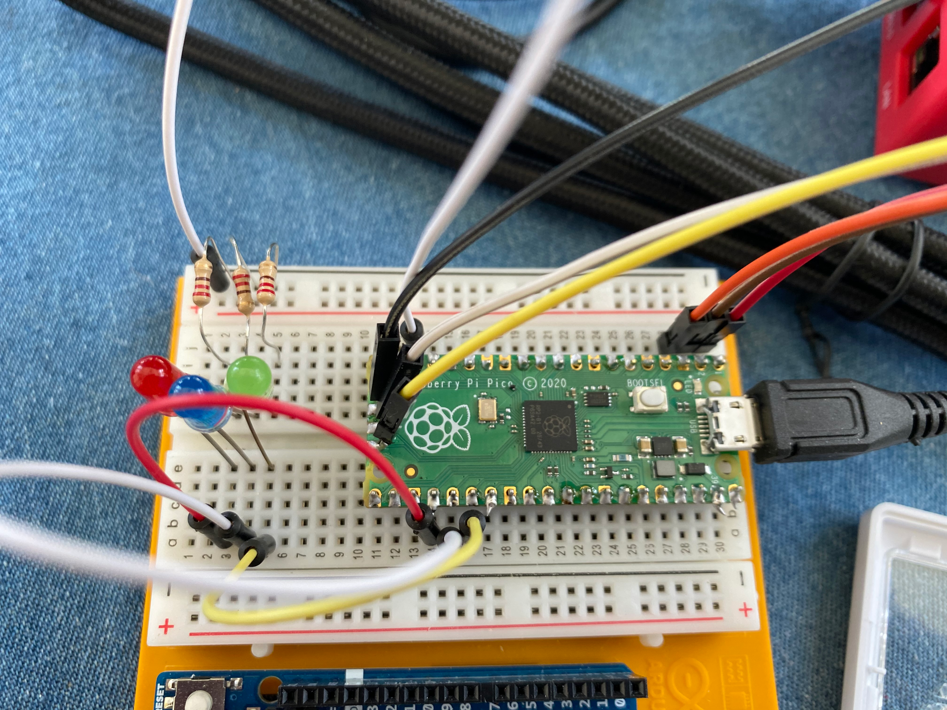
In the picture above you can also see the 3 wires at the end going off to the Raspberry Pi as well as the three wires by the USB port that lead to serial communications GPIO pins on the Pi. The USB connects to the Pi to provide power, as well as is used to load any program into the flash memory.
A single picture can be hard to see, here is a video showing the LEDs flashing as well as panning around a bit to see all the connections from different angles: https://youtu.be/ogbcMp5Asu4
Code
The C/C++ SDK for the RP2040 provides a set of libraries to help with your device programming along with support for using the GCC toolchain. This means you can write code in C/C++ and Assembly Language and then debug using gdb. If you look at the C code, it is similar to the code we wrote for the regular Raspberry Pi here, though we had to write some of these library type routines against the Linux device driver ourselves.
Here is the C code:
#include <stdio.h>
#include “pico/stdlib.h”
#include “hardware/gpio.h”
#include “pico/binary_info.h”
const uint LED_PIN1 = 18;
const uint LED_PIN2 = 19;
const uint LED_PIN3 = 20;
int main()
{
bi_decl(bi_program_description(“Copyright (c) 2021 Stephen Smith”));
stdio_init_all();
gpio_init(LED_PIN1);
gpio_init(LED_PIN2);
gpio_init(LED_PIN3);
gpio_set_dir(LED_PIN1, GPIO_OUT);
gpio_set_dir(LED_PIN2, GPIO_OUT);
gpio_set_dir(LED_PIN3, GPIO_OUT);
while (1)
{
puts(“Flash Loop\n”);
gpio_put(LED_PIN1, 1);
sleep_ms(200);
gpio_put(LED_PIN1, 0);
sleep_ms(200);
gpio_put(LED_PIN2, 1);
sleep_ms(200);
gpio_put(LED_PIN2, 0);
sleep_ms(200);
gpio_put(LED_PIN3, 1);
sleep_ms(200);
gpio_put(LED_PIN3, 0);
sleep_ms(200);
}
}
The SDK defines projects using CMake. When you run CMake it will generate a makefile that you use to build your executable using make. Here is the CMake file:
cmake_minimum_required(VERSION 3.13)
include(pico_sdk_import.cmake)
project(test_project C CXX ASM)
set(CMAKE_C_STANDARD 11)
set(CMAKE_CXX_STANDARD 17)
pico_sdk_init()
add_executable(flashleds
flashleds.c
)
pico_enable_stdio_uart(flashleds 1)
pico_add_extra_outputs(flashleds)
target_link_libraries(flashleds pico_stdlib)
Print Statements
In the C code there is a puts() function call to send “Flash Loop” to stdout. You can define what this is in the CMake file, in our case it’s set to the serial port (as opposed to the USB port). We can then read this data by monitoring the serial port on the Raspberry Pi 4 that we’ve connected up. One way to display the output is with the minicom program by calling:
minicom -b 115200 -o -D /dev/serial0
Which then displays:

Debugging
The Pico and the C/++ SDK have support for gdb. You run gdb on the Raspberry Pi 4 and then gdb connects remotely through minicom to the Raspberry Pi Pico. The C tutorial has full instructions on how to do this and when running it works quite well, though it takes several long command lines to get debugging going.
Visual Studio Code
The C/C++ SDK has full support for Visual Studio Code. This is the reason Raspberry added Microsoft repositories to the Raspberry Pi OS to seamlessly install and update this. After all the outcry from users, the calls to the Microsoft repositories have been removed and you need to install this by hand, as documented in the C getting started manual. I’m not really keen on Visual Studio Code, but if you like it and want to use it, go for it.
The best thing about Visual Studio Code is that it automates setting up remote debugging, so you can just say debug and Visual Studio Code does all the setup and connecting behind the scenes.
Summary
Both the Raspberry Pi Pico and Adafruit Feather RP2040 are powerful computers and great value as $5 microcontrollers. The programming environments are rich and powerful. You have lots of choices on how to program these with a lot of good supporting libraries and SDKs. The RP2040 exposes all sorts of GPIO ports and interfacing technology for you to make use of in your projects. It will be interesting to see all the RP2040 based DIY projects being showcased.
For people using this SDK, you can program in 32-bit ARM Assembly Language and might want to consider my book “Raspberry Pi Assembly Language Programming”.

[…] Raspberry Pi Pico first project – smist08.wordpress.com. […]
ICYMI Python on Microcontrollers Newsletter: The Adafruit Learn System Project Bundle, and more! #Python #Adafruit #CircuitPython @micropython @ThePSF #ICYMI « Adafruit Industries – Makers, hackers, artists, designers and engineers!
April 14, 2021 at 6:32 am
[…] those in the article. We’ll write an Assembly Language version of the program we wrote in C last time to flash three connected […]
Assembly Language on the Raspberry Pi Pico | Stephen Smith's Blog
April 16, 2021 at 9:43 am
Cheers
Bleugh
May 4, 2021 at 5:51 am
[…] Studios sent me one of their Grove Starter Kits for the Raspberry Pi Pico to review. The goal of this kit is to make working with microcontrollers accessible for educational […]
Playing with the Seeed Studio Grove Starter Kit for the Raspberry Pi Pico | Stephen Smith's Blog
October 12, 2021 at 10:08 am
[…] and goes into detail on how to program Raspberry’s RP2040 SoC. This chip is used in the Raspberry Pi Pico along with boards from several other manufacturers such as Seeed Studios, AdaFruit, Arduino and […]
RP2040 Assembly Language Programming | Stephen Smith's Blog
November 5, 2021 at 10:42 am
[…] a chapter on adding Assembly Language to MicroPython, a popular programming environment in the Raspberry Pi Pico world. In this article we’ll look at adding a simple Assembly Language function to the […]
Adding Assembly Language to MicroPython | Stephen Smith's Blog
February 18, 2022 at 3:33 pm
[…] the end of June, the Raspberry Pi foundation released a new version of the Raspberry Pi Pico that includes a wireless communications chip. This new Pico is named the Raspberry Pi Pico W and […]
Introducing the Raspberry Pi Pico W | Stephen Smith's Blog
August 26, 2022 at 11:30 am