Archive for the ‘rp2040’ Category
Assembly Language Tutorial Five for MagPi Magazine
I’m in the process of writing a series of Assembly Language tutorials for MagPi Magazine. The fifth one appeared in issue #120 on page 52.

The PDF version of the magazine is free to download, but MagPi always appreciates any donations.
This article leads readers through how to access the Raspberry Pi Pico’s hardware by reading and writing to special memory addresses that double as hardware access and status registers. This is typical of how the ARM processor is interfaced to hardware devices. Since the Raspberry Pi Pico doesn’t run an operating system, our program can directly access the hardware rather than going through device drivers or an SDK. In this tutorial we read temperature values directly from the Raspberry Pi Pico’s built in temperature sensor using Assembly Language. We write this code in the form of a function and call it from a C program that prints out the values for us to read.
This tutorial can only give so much detail. If you want more detail, you can always consider my book RP2040 Assembly Language Programming.


Adding Assembly Language to MicroPython
Introduction
My book “RP2040 Assembly Language Programming”, covered how to interact with modules written in compiled languages like C. However, there isn’t a chapter on adding Assembly Language to MicroPython, a popular programming environment in the Raspberry Pi Pico world. In this article we’ll look at adding a simple Assembly Language function to the MicroPython program we presented in “Playing with the Seeed Studio Grove Starter Kit for the Raspberry Pi Pico”. We’ll place the temperature and humidity together on the first line and then calculate their sum and output that on the second line.

Assembly Language in MicroPython
MicroPython has a syntax to add ARM “Thumb” Assembly Language instructions directly into your Python source code. This is great if you are using an ARM M-series based microcontroller such as Raspberry’s RP2040 or the Seeed Studio Wio Terminal which is based on an ARM M4 CPU. You specify that a function will be in Assembly Language by placing the directive:
@micropython.asm_thumb
before the function definition. The parameters to the Assembly Language function must be r0, r1, r2 & r4, allowing up to four arguments that are all 32-bit integers, other data types aren’t supported. The return value for the function will be whatever is in r0. Our simple Assembly Language function is:
@micropython.asm_thumb
def sum(r0, r1):
    add(r0, r0, r1)
Notice how the Assembly Language instructions are entered as functions to conform to Python syntax, though MicroPython compiles these directly to Assembly Language. There is a function for each instruction in the ARM M-series Thumb instruction set, including the floating point instructions, in case your microcontroller has a floating point unit such as in M4 based systems like the Wio Terminal. The MicroPython documentation for this is quite good and available here.
There is a separate label() function to define labels so you can create loops. You can access constants defined in the main Python program and use the << operator to specify shifts where they are allowed. There is a data() function to define data and an align() function to define alignment.
Inside our Assembly Language function, we can create additional functions and BL to them, and BX to return.
Next is the complete MicroPython program for this project.
from lcd1602 import LCD1602
from dht11 import *
from machine import Pin, I2C
from time import sleep
import math
i2c = I2C(1,scl=Pin(7), sda=Pin(6), freq=400000)
d = LCD1602(i2c, 2, 16)
dht2 = DHT(18) #temperature and humidity sensor connect to D18 po0rt
@micropython.asm_thumb
def sum(r0, r1):
    add(r0, r0, r1)
while True:
    temp,humid = dht2.readTempHumid()
    d.home()
    d.print("T,H:  " + str(temp) +" " + str(humid))
    d.setCursor(0, 1)
    d.print("Sum: " + str(sum(temp, humid)))
    sleep(0.5)
Notice that in our program, we didn’t need to build a custom version of MicroPython to include our routine, our program is strictly a MicroPython source file. This allows you to add Assembly Language functions to any build of MicroPython without requiring any rebuilding or worrying about conflicting versions.
Limitations & Uses
The main complaint I’ve seen about this is that you don’t have access to the RP2040 SDK, this is compiled into MicroPython and MicroPython doesn’t expose it for use. The best use for this is smaller functions that specifically optimize some aspect of Python that is slow, or access hardware registers that don’t have MicroPython libraries. Another use is to call specific Assembly Language instructions that there isn’t something corresponding to MicroPython. Similarly you can’t build other libraries into MicroPython and then call them directly from Assembly Language, you have to have MicroPython mediate access. There are tools like the Zerynth/Viper Emitter to generate your initial code, which can be helpful.
Another limitation is that you can’t write PIO Assembly Language for the RP2040’s programmable I/O.
Summary
Most people looking to use MicroPython, don’t want to mess with C or Assembly Language. They are using MicroPython to make their microcontroller projects easier. However, if you are stuck, this is a great way out of nearly any problem. Similarly, if you are writing a MicroPython interface for custom piece of hardware, this could be necessary to hit the hardware registers correctly. The MicroPython inline Assembly Language is a nice extension to the language and gives programmers great power from this system, but it is limited to ARM M-series type microcontrollers.
RP2040 Assembly Language Programming
Introduction
My third book on ARM Assembly Language programming has recently started shipping from Apress/Springer, just in time for Christmas. This one is “RP2040 Assembly Language Programming” and goes into detail on how to program Raspberry’s RP2040 SoC. This chip is used in the Raspberry Pi Pico along with boards from several other manufacturers such as Seeed Studios, AdaFruit, Arduino and Pimoroni.
Flavours of ARM Assembly Language
ARM has ambitions to provide CPUs from the cheapest microcontrollers costing less than a dollar all the way up to supercomputers costing millions of dollars. Along the road to this, there are now three distinct flavours of ARM Assembly Language:
- A Series 32-bit
- M Series 32-bit
- 64-bit
Let’s look at each of these in turn.
A Series 32-bit
For A Series, each instruction is 32-bits in length and as the processors have evolved they added features to support virtual memory, advanced security and other features to support advanced operating systems like Linux, iOS and Android. This is the Assembly Language used in 32-bit phones, tablets and the Raspberry Pi OS. This is covered in my book “Raspberry Pi Assembly Language Programming”.
M Series 32-bit
The full A series instruction set didn’t work well in microcontroller environments. Using 32-bits for each instruction was considered wasteful as well as supporting all the features for advanced operating systems made the CPUs too expensive. To solve the memory problem, ARM introduced a mode to A series 32-bit where each instruction was 16-bits, this saved memory, but the processors were still too expensive. When ARM introduced their M series, or microcontroller processors, they made this 16-bit instruction format the native format and removed most of the advanced operating system features. The RP2040 SoC used in the Raspberry Pi Pico is one of these M Series CPUs using dual core ARM Cortex M0+ CPUs. This is the subject of my current book “RP2040 Assembly Language Programming”.
64-bit
Like Intel and AMD, ARM made the transition from 32-bit to 64-bit processors. As part of this they cleaned up the instruction set, added registers and created a third variant of ARM Assembly Language. iOS and Android are now fully 64-bit and you can run 64-bit versions of Linux on newer Raspberry Pis. The ARM 64-bit instruction set is the topic of my book: “Programming with 64-Bit ARM Assembly Language”.
ARM 64-bit CPUs can run the 32-bit instruction set, and then the M series instruction set is a subset of the A series 32-bit instruction set. Each one is a full featured rich instruction set and deserves a book of its own. If you want to learn all three, I recommend buying all three of my books.
More Than ARM CPUs
The RP2040 is a System on a Chip (SoC), it includes the two M-series ARM CPU cores; but, it also includes many built in hardware interfaces, memory and other components. RP2040 boards don’t need much beyond the RP2040 chip besides a method to interface other components.
“RP2040 Assembly Language Programming” includes coverage of how to use the various hardware registers to control the built-in hardware controllers, as well as the innovative Programmable I/O (PIO) hardware coprocessors. These PIO coprocessors have their own Assembly Language and are capable of some very sophisticated communications protocols, even VGA.
Where to Buy
“RP2040 Assembly Language Programming” is available from most booksellers including:
- Apress/Springer Publishing Directly
- Amazon.com
- Amazon.ca
- Amazon.co.uk
- Amazon.com.au
- Indigo Books
- Barnes & Noble
- Book Depository
Currently if you search for “RP2040” in books on any of these sites, my book comes up first.
Summary
The Raspberry Pi Pico and the RP2040 chip aren’t the first ARM M-series based microcontrollers, but with their release, suddenly the popularity and acceptance of ARM processors in the microcontroller space has exploded. The instruction set for ARM’s M-series processors is simple, clean and a great example of a RISC instruction set. Whether you are into more advanced microcontroller applications or learning Assembly Language for the first time, this is a great place to start.
Playing with the Seeed Studio Grove Starter Kit for the Raspberry Pi Pico
Introduction
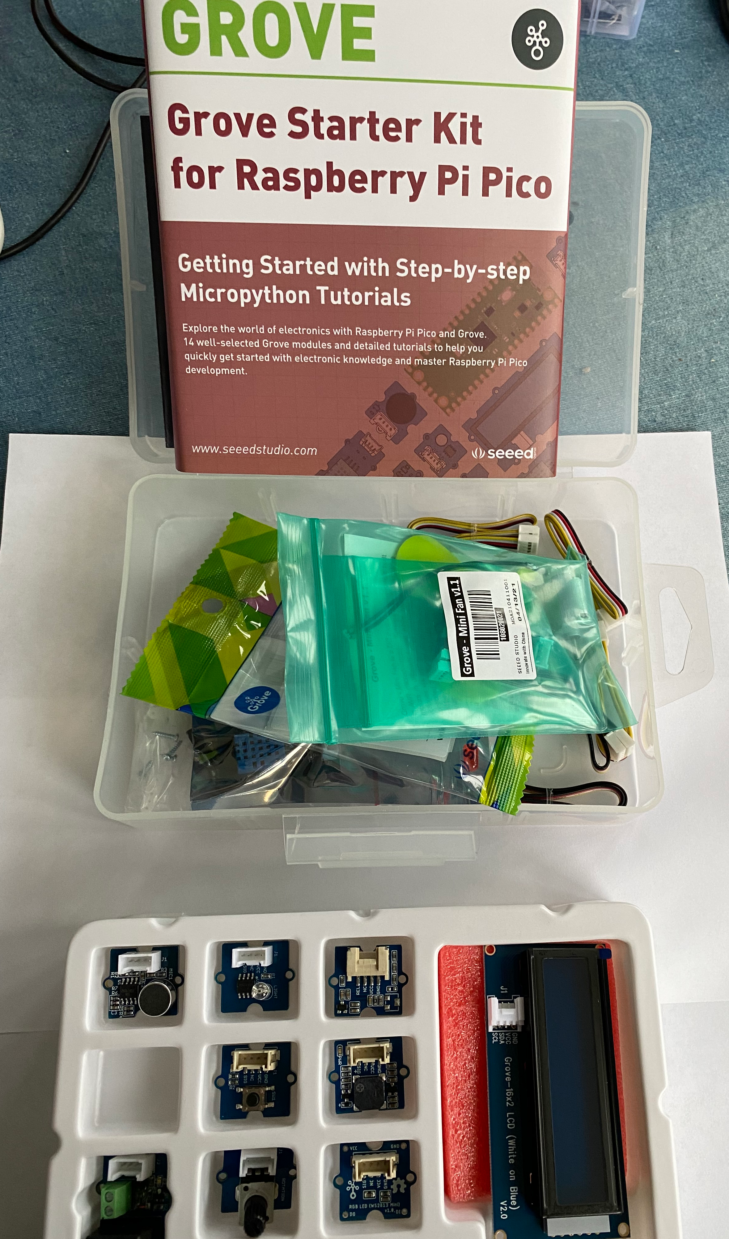
Seeed Studios sent me one of their Grove Starter Kits for the Raspberry Pi Pico to review. The goal of this kit is to make working with microcontrollers accessible for educational purposes. No soldering is required, everything snaps together and away you go. This starter kit comes with a carrier board for the Raspberry Pi Pico (sold separately), a number of connector cables and a selection of devices you can connect up.
What is Grove?
Grove is a standardized connector to allow you to connect devices to a microcontroller using a standard cable using four wires. This is similar to how you can connect devices to your laptop via USB cables. Modern microcontrollers like the various Arduino boards and the Raspberry Pi Pico have pins for multiple communications protocols as well as some general purpose digital and analog connections. The Grove connectors standardize how to wire up a number of these including:
- UART for standard serial communications
- I2C for synchronous serial communications
- Digital includes a wire for power, ground and primary and secondary digital signals
- Analog includes a wire for power, ground and primary and secondary analog signals
Seeed manufactures carrier boards for several common microcontroller boards. In this case the Raspberry Pi Pico.

The Raspberry Pi Pico fits into the inside pins in the two rows of pin receptors. You can use the outside rows to bypass the Grove connectors and wire the Pico to a breadboard as normal. The Grove ports provide three analog ports, three digital ports, two UARTs and two I2C. There are also breakouts for SPI and debug. Note that the Raspberry Pi Pico I have doesn’t have headers for the debug ports, so doesn’t make use of the debug receptors on this carrier. If you want to avoid soldering altogether, you need to purchase a Pico with pre-soldered headers such as this one.
The carrier board doesn’t have any active components, the PCB routes the pins on the Pico to the correct parts of each Grove connector.

If you are familiar with the Raspberry Pi Pico, you might know that most of the pins have multiple functions so you can make maximum use of the various pins. The Grove configuration is hardwired for one configuration and if you want to do something different then you need to connect to a breadboard or do some soldering. However, the Grove ecosystem provides lots of devices to connect up here and if you are living in the Grove world then this isn’t a problem.
Sample Program
Seeed’s web page to introduce the Starter Kit has lots of sample projects and I thought as a quick test, I’d wire up the temperature and humidity sensor along with the two line LCD display, I ran into an immediate problem that the sample project on the website was for a different LCD display than included in the kit. However modifying the code for the correct LCD display was fairly easy, mostly looking at one of the other sample projects. I suspect the components might be swapped in and out as supply and demand changes and the web site has trouble keeping up to date.

The direct support for Grove is via MicroPython, with Seeed promising to support Arduino C support sometime soon. You could program this with the RP2040 SDK, since there is direct support for all these devices, but the emphasis here is on educational settings and MicroPython. You need to have the Raspberry Pi Pico connected to a host computer via a micro-USB cable, I used my Windows 10 laptop for this. You write your program in the Thonny Python IDE, which has good support for the Pico, including installing the MicroPython runtime. The Pico version of MicroPython has good low level device support for the RP2040, which means it already knows how to talk to I2C, UARTs, digital and analog devices. Seeed provides MicroPython classes that provide a higher level interface to the various Grove devices included in the starter kit. Below is the source code for reading the temperature and humidity and displaying it on the LCD. The lcd1602.py and dht11.py files are the high level Python classes that Seeed provides for the LCD and digital humidity/temperature sensor.
from lcd1602 import LCD1602
from dht11 import *
from machine import Pin, I2C
from time import sleep
i2c = I2C(1,scl=Pin(7), sda=Pin(6), freq=400000)
d = LCD1602(i2c, 2, 16)
dht2 = DHT(18) #temperature and humidity sensor connect to D18 port
while True:
temp,humid = dht2.readTempHumid() #temp: humid:
d.home()
d.print(“Temp: ” + str(temp)) #display temperature on line 1
d.setCursor(0, 1)
d.print(“Humid: ” + str(humid))
sleep(0.5)
To get this project going, you connect the devices, using the Grove connector cables, enter this small Python program and away you go. Who knew building a microprocessor project and programming it could be so easy?
Summary
Building and programming microprocessor projects can be intimidating, involving soldering small fiddly wires and then writing programs in C and Assembly Language. Seeed simplifies this process by replacing soldering with simple standard connectors and then combines this with simplifying MicroPython high level classes to make the programming simpler. For learning and prototyping DIY projects this is great. This opens the educational potential to younger children, where you might be scared to give them a soldering iron. Further, you are less likely to get parts broken or lost. The Raspberry Pi Pico with its powerful RP2040 CPU runs MicroPython effortlessly and there is plenty of memory for quite large projects.
ARM’s True RISC Processors
Introduction
I recently completed my book, “RP2040 Assembly Language Programming” and was thinking about the differences in the three main instruction sets available on ARM Processors:
- The “thumb” instructions used in ARM’s 32-bit microcontrollers are covered in “RP2040 Assembly Language Programming”.
- The full 32-bit A-series instruction set as used by the Raspberry Pi OS is covered in my book “Raspberry Pi Assembly Language Programming”.
- The 64-bit instruction set used on all smartphones and tablets covered in my book “Programming with 64-Bit ARM Assembly Language”.
ARM is advertised as Reduced Instruction Set Computer (RISC) as opposed to Intel x86 chips which are Complex Instruction Set Computers (CISC). However, as ARM instroduces v9 of their full chip architecture, the instruction set has gotten pretty complex. Writing the RP2040 book and writing the included source code was nice in that the microcontroller version of the instruction set really is reduced and much simpler than the other two full versions. In this article, we’ll look at a bit of history of the various ARM instruction sets and why ARM is still considered a RISC processor.
A Bit of History
Originally, ARM was developed as a replacement to the 6502 processor used in the BBC Microcomputer, developed by Acorn. The early versions were specialty chips and it wasn’t until ARM was selected by Apple to use ARM in their Newton PDAs that ARM was spun off as a separate company starting with their 32-bit RISC CPUs. They reached the next level of success as Apple continued to use them in their iPods and then they hit it big when they were used in the iPhone and after that pretty much every smartphone and tablet that reached any level of success.
The original 32-bit instruction set used 32-bits to contain each machine instruction, which worked great as long as you had sufficient memory. In the microcontroller world there were complaints that for devices with only 4k of memory, these instructions were too big. To answer this, ARM added “thumb” instructions which were 16-bits in length, using half the memory of hte full instructions. The processor was still 32-bits, since the registers were 32-bits in size and all integer arithmetic was 32-bit. The “thumb” instruction set is a subset of the full 32-bit instruction set and the processor can switch between regular and thumb mode on select branch instructions. This allowed the microcontroller people to use the “thumb” subset to develop compact applications for their use. Even on computers with larger memory, “thumb” instructions can be useful since loading 16-bit instructions means you can load two instructions for each memory read and save contention on the memory bus and allowing twice as many instructions to fit in the instruction cache, improving performance.
The first “thumb” instruction set wasn’t complete which meant programs had to revert to full instructions to complete a number of functions. To address this ARM developed “thumb-2” to allow complete functionality without switching back. The various “thumb” instruction sets are all 32-bit, the 64-bit version of the ARM instruction set has no “thumb” subset.
Enter Microcontrollers
ARM has alway had the ambition to provide CPU chips covering the whole market from inexpensive small microcontrollers all the way up to the most powerful datacenter server chips. The full 32-bit ARM processors were a bit too expensive and complicated for the microcontroller market. To address this market, ARM developed the M-series CPUs where they chose to make the full instruction set of these devices, the “thumb” instruction set. This made these CPUs far simpler and required fewer transistors to create. This laid the way for powerful ARM 32-bit CPUs for the microcontroller market costing under $1 each.
For instance, the ARM Cortex-M0+ used in the Raspberry Pi Pico has 85 instructions. This sounds like a lot, but it counts things like adding a register to a register different from adding an immediate operand to a register. This is far fewer instructions than in an ARM full A-series processor, which is far fewer than the instructions in an x86 processor.
Some of the features that are dropped from the M-series processors are:
- Virtual memory
- Hardware memory protection
- Virtualization
- Conditional instructions
- Not all instructions can address all the registers
- Immediate operands are much smaller and shifting isn’t supported
- The addressing modes are far simpler
- Instructions either set or don’t set the conditional flags, there is no extra bit to control this
Most microcontrollers run a single program that has access to all the memory, so these aren’t an issue. However, the lack of hardware hasn’t stopped people adding software support and implementing Linux and other OS’s running on these microcontrollers.
Are ARM Processors Still RISC?
A full ARM A-Series processor like those found in the Raspberry Pi, Apple’s iPhone 7 iPad along with dozens of Android and ChromeOS devices, all run the full 64-bit instruction set, as well as the full 32-bit instruction set including the “thumb” instruction. They support virtual memory, virtualization, FPUs, vector processors, advanced security and everything else you would expect in a modern processor. That is a lot for something that is billed as “reduced”. Basically an ARM CPU has the same transistor budget as an x86 processor, so they use every transistor to do something useful. So why are ARM processors still considered RISC? The parts of RISC that all ARM processors retain is:
- The instructions are a fixed length.
- They are a load/store architecture (no instructions like add memory to register). An instruction either loads/stores from memory or performs an arithmetic operation on the registers.
- Most instructions execute in a single clock cycle.
- They have a large set of registers, though Intel processors now also have a large set of registers.
Even with all this functionality, ARM processors use far less power than x86 processors, this is mainly due to the simplifications that fixed length instructions and a load/store architecture provide. Intel processor now execute a RISC processor at their core, but then have to add another layer to translate each x86 instruction into their internal RISC instructions, that all uses transistors and power when executing,
So yes, even though the number of instructions in an ARM CPU has multiplied greatly over the nine generations of the chips, the core ideas are still RISC.
Summary
The line of M-series ARM CPUs are far simpler to program than the full A-Series. There is no virtual memory support, so you can access hardware addresses directly, reading and writing anywhere without worries about security or memory protection. The instruction set is simpler and nothing is wasted. Having written three books on ARM Assembly Language Programming, I think learning Assembly Language for a microcontroller is a great way to start. You have full control of the hardware and don’t have to worry about interacting with an operating system. I think you get a much better feel for how the hardware works as well as a real feel for programming for RISC based processors. If you are interested in this, I hope you check out my forthcoming book: “RP2040 Assembly Language Programming”.

Introducing the Seeed Studio Wio RP2040
Introduction
When the Raspberry Pi Foundation designed their new microcontroller, the Raspberry Pi Pico, the heart of the board is the RP2040 System on a Chip (SoC). This chip contains dual ARM Cortex-M0+ CPU cores, 296kb RAM, a number of coprocessors and a number of specialty I/O processors. Raspberry made the decision to sell this chip separately and it has since appeared on the boards from various other hardware vendors. Previously, we discussed the Adafruit Feather RP2040 and in this article is about Seeed Studio’s Wio RP2040 which is another of these boards. The Raspberry Pi Pico contains support for several wired communications protocols, but no support for wireless communications, or ethernet, making it difficult to connect directly to the Internet. Seeed Studio paired the RP2040 chip with a ESP based wireless chip, adding both WiFi and Bluetooth in a board smaller than the Pico.
Update (2021/12/23): Seeed Studio has released another RP2040 based board, the XIAO RP2040. It runs at up to 133MHz, is built with rich interfaces in a tiny thumb size, and fully supports Arduino, MicroPython, and CircuitPython. The onboard interfaces are enough for developing multiple applications with pins compatible with Seeeduino XIAO and supports Seeeduino XIAO’s Expansion board.
Module vs Development Board
There are two versions of of the Wio RP2040 board:
- The Wio RP2040 Module containing the RP2040

- The Wio RP2040 Mini Dev Board which adds a bootsel button, led, usb connector, and the pins to add it to a breadboard.

If you are experimenting, I would recommend getting the development board. If you get the CPU module then at a minimum you need to solder the wires for a USB wire to the board so you can connect it to a host computer to download programs from.
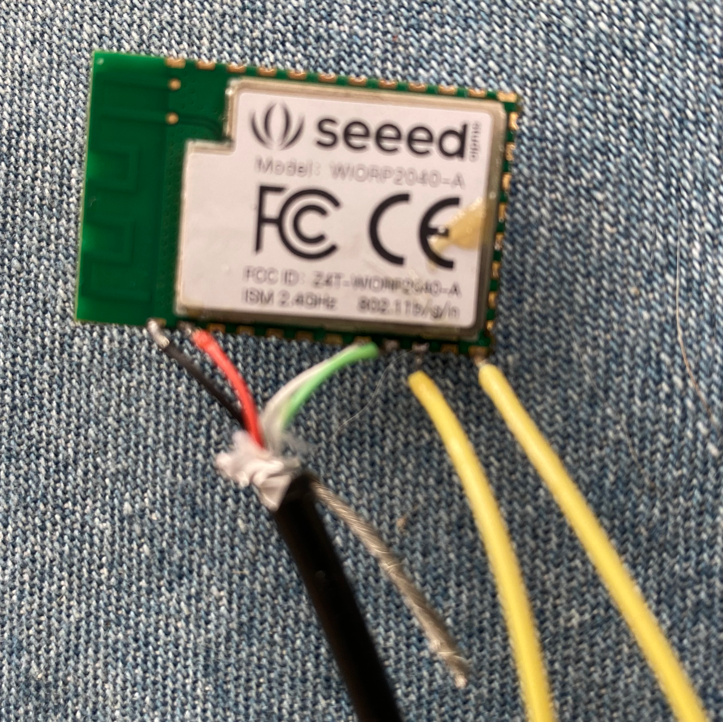
I received the module version, so I learned a bit about the four wires contained in a USB cable. Fortunately, there is a standard for the wire colors, so figuring out the wiring was easy. Soldering the USB cable to the module was fiddly but doable. You also need to solder two wires for the bootsel button, you can either connect these to a button, or just touch them together to activate bootsel. If you want to debug with gdb, then you also need to connect three wires to the two SWD pins and a ground pin, to allow gdb to control the board.
Below is my module with the USB cable soldered in and two leads for the bootsel button. I should add three more wires for debugging, but this isn’t necessary if you are only using MicroPython.

Software Development
The core of this board is the RP2040 processor, so you can develop with this board using Raspberry’s RP2040 SDK. You can also use any of the environments that support the Raspberry Pi Pico like MicroPython or the Arduino system. The only restriction is that WiFi support is only officially supported with MicroPython which we talk about next.
Developing with WiFi
As of this writing, using the WiFI/Bluetooth functionality is only supported from MicroPython. Seeed supplies a custom version of MicroPython which has this module compiled in. This version leverages the work in MicroPython done for the Raspberry Pi Pico and as a consequence works with the Thonny Python IDE. This is an interesting contrast with Seeed’s Wio Terminal which doesn’t have IDE support and you need to rely on REPL for development.
The problem with this approach is that I couldn’t find the source code for this build of MicroPython, which means if I wanted to add more libraries, I don’t have a way to do this, including my own custom C and Assembly Language code. Again, contrast this to the Wio Terminal, which includes all the source code as well as a build system for adding modules and custom code. Hopefully, the source code for this MicroPython build makes it onto Seeed’s Github repository in the near future.
There is speculation on the forums that the WiFi is an ESP8266 board connected via the SPI interface and then controlled using AT commands. These are basically an extension of the old Hayes modem command set, extended to a more modern world. It wouldn’t take much documentation on Seeed’s part to provide some details, such as the SPI port used and SPI configuration parameters. With this detail it would be easy to add WiFi and/or Bluetooth support to programs written in the standard RP2040 SDK. Or better still contribute their WiFi support to the Raspberry Pi Pico Extras GitHub repository.
Summary
The Seeed Wio RP2040 is a compact module to build your projects around. The big current limitation is the lack of software support for the ESP radio module; hopefully, this will be rectified in the near future. Seeed designed this module to be included into custom PCB boards such as their dev board and offer a service to manufacture these. If this is your first Wio RP2040, then you should get the mini dev board as this is far easier to connect up and get working, then use the smaller module in your final project.
I/O Co-processing on the Raspberry Pi Pico
Introduction
Last time we looked at how to access the RP2040’s GPIO registers directly from the CPU in Assembly Language. This is a common technique to access and control hardware wired up to a microcontroller’s GPIO pins; however, the RP2040 contains a number of programmable I/O (PIO) coprocessors that can be used to offload this work from the main ARM CPUs. In this article we’ll give a quick overview of the PIO coprocessors and present an example that moves the LED blinking logic from the CPU over to the coprocessors, freeing the CPU to perform other work. There is a PIO blink program in the SDK samples, which blinks three LEDs at different frequencies, we’ll take that program and modify it to blink the LEDs in turn so that it works the same as the examples we’ve been working with.
PIO Overview
There are eight PIO coprocessors divided into two banks for four. Each bank has a single 32 word instruction memory that contains the program(s) that run on the coprocessors. 32 instructions aren’t very many, but you can do quite a bit with these. The SDK contains samples that implement quite a few communication protocols as well as showing how to do video output.
Each PIO has an input and output FIFO buffer for exchanging data with the main CPUs.
The PIO coprocessors execute their own Assembly Language which the Raspberry folks call a state machine, though they also say they think it is Turing-complete. Below is a diagram showing one of the banks of four. This block is then duplicated twice in the RP2040 package.

Each processor has an X and Y 32-bit general purpose register, input and output shift registers for transferring data to and from the FIFOs, a clock divider register to help control timing, a program counter and then the register to hold the executing instruction as shown in the following diagram.

Each instruction can contain a few bits that specify a delay value, so for many protocols you can control the timing just by adding a timing delay to each instruction. Combine this with the clock divider register to slow down processing and you have a lot of control of timing without using extra instructions.
Sample LED Blinking Program
You write the Assembly Language PIO part of the program into a .pio file which is then compiled by the PIO Assembler into a .h file to include into your program. You can also include C helper functions here and the Pico SDK recommends including an initialization function. The various RP2040 SDK functions to support this are pretty standard and you tend to copy/paste these from the SDK samples.
We are blinking the LEDS using a 200ms delay time which by computer speeds is very slow, but for humans is quite quick. This means we can’t use the clock divider functionality and instruction delays as they don’t go this slow. Instead we have to rely on an old fashioned delay loop. We calculated the delay value in the main function using the frequency of the processor and then doing a loop. We do this delay loop twice because we need to wait for two other LEDs to flash before it’s our turn again. The pull instruction pulls the delay from the read FIFO, then out transfers it to the y register. We move y to x, turn on the pin and then do the delay loop decementing x until its zero. Then we turn the pin off and do the delay loop twice.
.program blink
pull block
out y, 32
.wrap_target
mov x, y
set pins, 1 ; Turn LED on
lp1:
jmp x– lp1 ; Delay for (x + 1) cycles, x is a 32 bit number
mov x, y
set pins, 0 ; Turn LED off
lp2:
jmp x– lp2 ; Delay for the same number of cycles again
mov x, y
lp3: ; Do it twice since need to wait for 2 other leds to blink
jmp x– lp3 ; Delay for the same number of cycles again
.wrap ; Blink forever!
% c-sdk {
// this is a raw helper function for use by the user which sets up the GPIO output, and configures the SM to output on a particular pin
void blink_program_init(PIO pio, uint sm, uint offset, uint pin) {
pio_gpio_init(pio, pin);
pio_sm_set_consecutive_pindirs(pio, sm, pin, 1, true);
pio_sm_config c = blink_program_get_default_config(offset);
sm_config_set_set_pins(&c, pin, 1);
pio_sm_init(pio, sm, offset, &c);
}
%}
Now the main C program. In this one we configure the pins to use. Note that we will use a coprocessor for each pin, so three coprocessors but each one executing the same program. We start a pin flashing, sleep 200ms and then start the next one. This way we achieve the same effect as we did in our previous programs.
After we get the LED flashing running on the coprocessors, we have an infinite loop that just prints a counter out to the serial port. This is to demonstrate that the CPU can go on and do anything it wants and the LEDs will keep flashing independently without any of the CPU’s attention.
#include <stdio.h>
#include “pico/stdlib.h”
#include “hardware/pio.h”
#include “hardware/clocks.h”
#include “blink.pio.h”
const uint LED_PIN1 = 18;
const uint LED_PIN2 = 19;
const uint LED_PIN3 = 20;
#define SLEEP_TIME 200
void blink_pin_forever(PIO pio, uint sm, uint offset, uint pin, uint freq);
int main() {
int i = 0;
setup_default_uart();
PIO pio = pio0;
uint offset = pio_add_program(pio, &blink_program);
printf(“Loaded program at %d\n”, offset);
blink_pin_forever(pio, 0, offset, LED_PIN1, 5);
sleep_ms(SLEEP_TIME);
blink_pin_forever(pio, 1, offset, LED_PIN2, 5);
sleep_ms(SLEEP_TIME);
blink_pin_forever(pio, 2, offset, LED_PIN3, 5);
while(1)
{
i++;
printf(“Busy counting away i = %d\n”, i);
}
}
void blink_pin_forever(PIO pio, uint sm, uint offset, uint pin, uint freq) {
blink_program_init(pio, sm, offset, pin);
pio_sm_set_enabled(pio, sm, true);
printf(“Blinking pin %d at %d Hz\n”, pin, freq);
pio->txf[sm] = clock_get_hz(clk_sys) / freq;
}
Summary
This was a quick introduction to the RP2040’s PIO coprocessors. The goal of any microcontroller is to control other interfaced hardware, whether measurement sensors or communications devices (like Wifi). The PIO coprocessors give the RP21040 programmer a powerful weapon to develop sophisticated integration projects without requiring a lot of specialized hardware to make things easier. It might be nice to have a larger instruction memory, but then in a $4 USD device, you can’t really complain.
For people playing with the Raspberry Pi Pico or another RP2040 based board, you can program in 32-bit ARM Assembly Language and might want to consider my book “Raspberry Pi Assembly Language Programming”.

Bit-Banging the Raspberry Pi Pico’s GPIO Registers
Introduction
Last week, I introduced my first Assembly Language program for the Raspberry Pi Pico. This was a version of my flashing LED program that I implemented in a number of programming languages for the regular Raspberry Pi. In the original article, I required three routines written in C to make things work. Yesterday, I showed how to remove one of these C routines, namely to have the main routine written in Assembly Language. Today, I’ll show how to remove the two remaining C routines, which were wrappers for two SDK routines which are implemented as inline C functions and as a consequence only usable from C code.
In this article, we’ll look at the structure for the GPIO registers on the RP2040 and how to access these. The procedure we are using is called bit-banging because we are using one of the two M0+ ARM CPU cores to loop banging the bits in the GPIO registers to turn them on and off. This isn’t the recommended way to do this on the RP2040. The RP2040 implements eight programmable I/O (PIO) co-processors that you can program to offload this sort of thing from the CPU. We’ll look at how to do that in a future article, but as a first step we are going to explore bit-banging mostly to understand the RP2040 hardware better.
The RP2040 GPIO Hardware Registers
There are 28 programmable GPIO pins on the Pico. There are 40 pins, but the others are ground, power and a couple of specialized pins (see the diagram below).

This means that we can assign each one to a bit in a 32-bit hardware register which is mapped to 32-bits of memory in the RP2040’s address space. The GPIO functions are controlled by writing a 1 bit to the correct position in the GPIO register. There is one register to turn on a GPIO pin and a different register to turn it off, this means you don’t need to read the register, change one bit and then write it back. It’s quite easy to program these since you just place one in a CPU register, shift it over by the pin number and then write it to the correct memory location. These registers start at memory location 0xd0000000 and are defined in sio.h. Note there are two sio.h files, one in hardware_regs which contains the offsets and is better for Assembly Language usage and then one in hardware_structs which contains a C structure to map over the registers. Following are the GPIO registers, note that there are a few other non-GPIO related registers at this location and a few unused gaps in case you are wondering why the addresses aren’t contiguous.
| Register | Address |
| gpio_in | 0xd0000004 |
| gpio_hi_in | 0xd0000008 |
| gpio_out | 0xd0000010 |
| gpio_set | 0xd0000014 |
| gpio_clr | 0xd0000018 |
| gpio_togl | 0xd000001c |
| gpio_oe | 0xd0000020 |
| gpio_oe_set | 0xd0000024 |
| gpio_oe_clr | 0xd0000028 |
| gpio_togl | 0xd000002c |
| gpio_hi_out | 0xd0000030 |
| gpio_hi_set | 0xd0000034 |
| gpio_hi_clr | 0xd0000038 |
| gpio_hi_togl | 0xd000003c |
| gpio_hi_oe | 0xd0000040 |
| gpio_hi_oe_set | 0xd0000044 |
| gpio_hi_oe_clr | 0xd0000048 |
| gpio_hi_oe_togl | 0xd000004c |
Notice that there are a number of _hi_ registers, perhaps indicating that Raspberry plans to come out with a future version with more than 32 GPIO pins.
In the SDK and my code below we just write one bit at a time, I don’t know if the RP2040’s circuitry can handle writing more bits at once, for instance can we set all three pins to output in one write instruction? Remember hardware registers tend to have minimal functionality to simplify the electronics circuitry behind them so often you can’t get too complicated in what you expect of them.
Bit-Banging the Registers in Assembly
Below is the new updated program that doesn’t require the C file. In our routines to control the GPIO pins, we pass the pin number as parameter 1, which means it is in R0. We place 1 in R3 and then shift it left by the value in R0 (the pin number). This gives the value we need to write. We then load the address of the register we need, which we specified in the .data section and write the value. Note that we need two LDR instructions, once to load the address of the memory address and then the second to load the actual value.
@
@ Assembler program to flash three LEDs connected to the
@ Raspberry Pi GPIO port using the Pico SDK.
@
@
.EQU LED_PIN1, 18
.EQU LED_PIN2, 19
.EQU LED_PIN3, 20
.EQU sleep_time, 200
.thumb_func
.global main @ Provide program starting address to linker
.align 4 @ necessary alignment
main:
@ Init each of the three pins and set them to output
MOV R0, #LED_PIN1
BL gpio_init
MOV R0, #LED_PIN1
BL gpiosetout
MOV R0, #LED_PIN2
BL gpio_init
MOV R0, #LED_PIN2
BL gpiosetout
MOV R0, #LED_PIN3
BL gpio_init
MOV R0, #LED_PIN3
BL gpiosetout
loop:
@ Turn each pin on, sleep and then turn the pin off
MOV R0, #LED_PIN1
BL gpio_on
LDR R0, =sleep_time
BL sleep_ms
MOV R0, #LED_PIN1
BL gpio_off
MOV R0, #LED_PIN2
BL gpio_on
LDR R0, =sleep_time
BL sleep_ms
MOV R0, #LED_PIN2
BL gpio_off
MOV R0, #LED_PIN3
BL gpio_on
LDR R0, =sleep_time
BL sleep_ms
MOV R0, #LED_PIN3
BL gpio_off
B loop @ loop forever
gpiosetout:
@ write a 1 bit to the pin position in the output set register
movs r3, #1
lsl r3, r0 @ shift over to pin position
ldr r2, =gpiosetdiroutreg @ address we want
ldr r2, [r2]
str r3, [r2]
bx lr
gpio_on:
movs r3, #1
lsl r3, r0 @ shift over to pin position
ldr r2, =gpiosetonreg @ address we want
ldr r2, [r2]
str r3, [r2]
bx lr
gpio_off:
movs r3, #1
lsl r3, r0 @ shift over to pin position
ldr r2, =gpiosetoffreg @ address we want
ldr r2, [r2]
str r3, [r2]
bx lr
.data
.align 4 @ necessary alignment
gpiosetdiroutreg: .word 0xd0000024 @ mem address of gpio registers
gpiosetonreg: .word 0xd0000014 @ mem address of gpio registers
gpiosetoffreg: .word 0xd0000018 @ mem address of gpio registers
Having separate functions for gpio_in and gpio_out simplifies our code since we don’t need any conditional logic to load the correct register address.
We loaded the actual address from a shared location. We could have loaded the base address of 0xd000000 and then stored things via an offset, but I did this to be a little clearer. If you look at the disassembly of the SDK routine, it does something rather clever to get the base address. It does:
movs r2, #208 @ 0xd0
lsl r2, r2, #24 @ becomes 0xd0000000
And then uses something like:
str r3, [r2, #40] @ 0x28
To store the value using an index which is the offset to the correct register. I thought this was rather clever on the C compiler’s part and represents the optimizations that the ARM engineers have been adding to the GCC generation of ARM code. This technique takes the same time to execute, but doesn’t require saving any values in memory, saving a few bytes which may be crucial in a larger program.
Summary
Writing to the hardware registers directly on the Raspberry Pi Pico is a bit simpler than the Broadcom implementation in the full Raspberry Pi. With these routines we wrote our entire program in Assembly Language. There is still C code in the SDK which will be linked into our program and we are still calling both gpio_init and sleep_ms in the SDK. We could look at the source code in the SDK and reimplement these in Assembly Language, but I don’t think there is any need. Between the RP2040 documentation and the SDK’s source code it is possible to figure out a lot about how the Raspberry Pi Pico works.
For people playing with the Raspberry Pi Pico or another RP2040 based board, you can program in 32-bit ARM Assembly Language and might want to consider my book “Raspberry Pi Assembly Language Programming”.
Calling Main in Assembly Language on the RP2040
Introduction
In last week’s article, I presented my first Assembly Language program on the Raspberry Pi Pico. The program worked, but it included some C code that I wasn’t happy with. In this article, I’ll explain why I needed to have the main entry point in C, what I missed and how to correct this problem.
The entry point is a function main() with no parameters or return code called by the RP2040 initialization code after it initializes the RP2040 hardware. In C this worked no problem, but in Assembly Language it resulted in a hardware fault on executing the first instruction in my main() routine. This was a bit of a head scratcher and it took a couple of days before I realized what the problem was. My first thought was that it was alignment, but no it wasn’t that. Perhaps I needed to duplicate the first few instructions in the Assembly Language generated by the C compiler, but no that still caused a hardware fault. Rather mystifying and annoying.

Use the Source
The program you run on the Pico contains pretty much everything in a single executable, that initializes the CPU, peripheral hardware and then runs in an endless loop forever. There is no operating system, just your program. The Raspberry Pi Pico contains a bit of firmware which is activated when you power on with the bootsel button pressed, this allows the Pico to connect as a shareable flash drive to a USB host, and will allow you to copy files into the writable part of the Pico’s flash memory. After that it reboots to let the program run.
One of the good things about the Pico is that the SDK contains the source code for this whole thing, and when you build your program, it actually compiles all this source code alongside your code (there are no libraries in this environment). This means you can build a debug build where everything is debuggable including both your code and the SDK code. This means you can set a breakpoint before your code and single step through the SDK into your code. You can’t start debugging at the very first instruction, you need to let the first bit of the SDK initialize the processor before starting, but you can set a breakpoint fairly early. I found a good place was the platform_entry routine, which is an Assembly Language function in crt0.S. This is the function that initializes the SDK environment and then calls your main() starting point. The code for this routine is fairly innocuous:
platform_entry: // symbol for stack traces
// Use 32-bit jumps, in case these symbols are moved out of branch range
// (e.g. if main is in SRAM and crt0 in flash)
ldr r1, =runtime_init
blx r1
ldr r1, =main
blx r1
ldr r1, =exit
blx r1
Nothing special, it just loads the address of our main routine and calls it. Stepping through the C code, it works, stepping through the Assembly Language code, hardware fault.
At some point I thought to look at the documentation for the BLX instruction, why were they calling this rather than BL? This turned out to be the root of the problem.
On a full ARM A-series CPU, like those in a full Raspberry Pi or in your cell phone, it can execute a rich set of instructions, which are the regular ARM 32-bit instruction set, but on the microcontroller M-series CPU like in the Pico it only executes the so called “thumb” instructions. On the A-series CPU you switch back and forth between regular and thumb modes using the BLX instruction. Thumb instructions are 16-bit in length, regular instructions are 32-bit, both have to be aligned, on even bytes the other on 4-byte boundaries. Both of these are even addresses so the true address of any instruction is even, which means the low order bit isn’t really used (it has to be zero). The BLX instruction uses this low order bit to specify whether to switch to thumb mode or not. If it is one, then thumb mode, if even then regular instruction mode. Let’s look at the disassembly for this routine:
1000021a <platform_entry>:
1000021a: 4919 ldr r1, [pc, #100] ; (10000280 <__get_current_exception+0x1a>)
1000021c: 4788 blx r1
1000021e: 4919 ldr r1, [pc, #100] ; (10000284 <__get_current_exception+0x1e>)
10000220: 4788 blx r1
10000222: 4919 ldr r1, [pc, #100] ; (10000288 <__get_current_exception+0x22>)
10000224: 4788 blx r1
10000280: 100012bd .word 0x100012bd ; runtime_init
10000284: 10000361 .word 0x10000360 ; main
10000288: 100013a9 .word 0x100013a9 ; exit
Notice the address for my main routine is even whereas the other two routines are odd. If I compile with the C routine then main has an odd address as well. I didn’t think of this because the RP2040’s M-series CPU only executes thumb instructions, so why have any functionality to switch between modes? I don’t know but if you do tell it to switch to regular instructions then you get a hardware fault.
The other question is why the author of crt0.S in the SDK calls routines with BLX rather than BL? Afterall the Pico doesn’t support regular instructions, so you are always in thumb mode. If platform_entry used BL instead, then I wouldn’t have had any problem. I wonder if this indicates they developed the SDK on an A-series CPU, perhaps before they obtained real RP2040’s and this indicates how they did early development on the SDK? Or perhaps there is a way to emulate the RP2040 on a full A-series CPU and this is how the developers at the Raspberry Pi foundation operate.
To correct the problem, we just need to indicate our main() routine is a thumb routine. We do this by placing a .thumb_func directive in front of the .global directive.
.thumb_func
.global main @ Provide program starting address to linker
.align 4 @ necessary alignment
main:
The key point is that this is in front of the .global, since it is really just the linker that needs to process this to set up the correct address when it links in crt0.
Summary
This eliminates the need for the C main() function we had last week. Next time we’ll eliminate the two other C routines we had and explore how the Raspberry Pi Pico’s GPIO control registers work. As with most problems, working through the solution, teaches us a bit more about how the RP2040 works and reminds us that there are consequences of using a subset of the full ARM instruction set.
For people using this SDK, you can program in 32-bit ARM Assembly Language and might want to consider my book “Raspberry Pi Assembly Language Programming”.
Raspberry Pi Pico First Project
Introduction
Last week, I blogged about Adafruit’s Feather RP2040 microcontroller. I’ve now received a Raspberry Pi Pico which is also based on the ARM RP2040 processor. The Adafruit version is oriented around programming with CircuitPython and then interfacing to the various companion boards in Adafruit’s Feather lineup. The Raspberry Pi Pico is oriented around programming in C/C++ using the Raspberry Pico SDK and then designing interfaces to other devices yourself. Although you can do either with both boards, I’m going by the direction of the two companies tutorials and volume of documentation. The Raspberry Pi Pico also favours doing your development from a full Raspberry Pi, although you can use a Windows, Linux or Mac, it is quite a bit harder to setup serial communications and debugging.
In this article, I’m going to look at doing a small project with the Raspberry Pi Pico using the C SDK. I’ll look at the elements you use to program, debug and deploy code. I’ll use the same flashing LEDs project that I’ve written about previously.
More Soldering
Like the Adafruit board, if you want to use a breadboard to set up your electronics project, you need to solder pins to the Pico to attach it. Having practiced on the Adafruit Feather, this was no problem. In addition if you want to do proper C debugging using gdb then you need to solder three wires to the debug ports on the end of the board. Note you need wires that can connect to the Raspberry Pi 4’s GPIO pins. All the soldering went fine and when I wired everything up I got serial communications going as well as played a bit with debugging using the SDK’s sample blink program. I was lucky that I could find all the wires, connectors and pins required from previous various Arduino and Raspberry starter kits.
Setting up the LEDs
If you want to use print statements while you are debugging, then you need to use the separate serial communications pins rather than a serial communications channel through the USB port. This is because when you stop the processor in the debugger, it stops it dead and disconnects any USB connections.
The picture below shows the setup. The LEDs are connected each to a GPIO port and then go through a resistor to ground. Remember LEDs have low resistance and you don’t want to short out your device. Also remember that LEDs are directional and you want to connect the plus side to the GPIO pin. The plus side is usually indicated by the longer lead wire.
In the picture above you can also see the 3 wires at the end going off to the Raspberry Pi as well as the three wires by the USB port that lead to serial communications GPIO pins on the Pi. The USB connects to the Pi to provide power, as well as is used to load any program into the flash memory.
A single picture can be hard to see, here is a video showing the LEDs flashing as well as panning around a bit to see all the connections from different angles: https://youtu.be/ogbcMp5Asu4
Code
The C/C++ SDK for the RP2040 provides a set of libraries to help with your device programming along with support for using the GCC toolchain. This means you can write code in C/C++ and Assembly Language and then debug using gdb. If you look at the C code, it is similar to the code we wrote for the regular Raspberry Pi here, though we had to write some of these library type routines against the Linux device driver ourselves.
Here is the C code:
#include <stdio.h>
#include “pico/stdlib.h”
#include “hardware/gpio.h”
#include “pico/binary_info.h”
const uint LED_PIN1 = 18;
const uint LED_PIN2 = 19;
const uint LED_PIN3 = 20;
int main()
{
bi_decl(bi_program_description(“Copyright (c) 2021 Stephen Smith”));
stdio_init_all();
gpio_init(LED_PIN1);
gpio_init(LED_PIN2);
gpio_init(LED_PIN3);
gpio_set_dir(LED_PIN1, GPIO_OUT);
gpio_set_dir(LED_PIN2, GPIO_OUT);
gpio_set_dir(LED_PIN3, GPIO_OUT);
while (1)
{
puts(“Flash Loop\n”);
gpio_put(LED_PIN1, 1);
sleep_ms(200);
gpio_put(LED_PIN1, 0);
sleep_ms(200);
gpio_put(LED_PIN2, 1);
sleep_ms(200);
gpio_put(LED_PIN2, 0);
sleep_ms(200);
gpio_put(LED_PIN3, 1);
sleep_ms(200);
gpio_put(LED_PIN3, 0);
sleep_ms(200);
}
}
The SDK defines projects using CMake. When you run CMake it will generate a makefile that you use to build your executable using make. Here is the CMake file:
cmake_minimum_required(VERSION 3.13)
include(pico_sdk_import.cmake)
project(test_project C CXX ASM)
set(CMAKE_C_STANDARD 11)
set(CMAKE_CXX_STANDARD 17)
pico_sdk_init()
add_executable(flashleds
flashleds.c
)
pico_enable_stdio_uart(flashleds 1)
pico_add_extra_outputs(flashleds)
target_link_libraries(flashleds pico_stdlib)
Print Statements
In the C code there is a puts() function call to send “Flash Loop” to stdout. You can define what this is in the CMake file, in our case it’s set to the serial port (as opposed to the USB port). We can then read this data by monitoring the serial port on the Raspberry Pi 4 that we’ve connected up. One way to display the output is with the minicom program by calling:
minicom -b 115200 -o -D /dev/serial0
Which then displays:

Debugging
The Pico and the C/++ SDK have support for gdb. You run gdb on the Raspberry Pi 4 and then gdb connects remotely through minicom to the Raspberry Pi Pico. The C tutorial has full instructions on how to do this and when running it works quite well, though it takes several long command lines to get debugging going.
Visual Studio Code
The C/C++ SDK has full support for Visual Studio Code. This is the reason Raspberry added Microsoft repositories to the Raspberry Pi OS to seamlessly install and update this. After all the outcry from users, the calls to the Microsoft repositories have been removed and you need to install this by hand, as documented in the C getting started manual. I’m not really keen on Visual Studio Code, but if you like it and want to use it, go for it.
The best thing about Visual Studio Code is that it automates setting up remote debugging, so you can just say debug and Visual Studio Code does all the setup and connecting behind the scenes.
Summary
Both the Raspberry Pi Pico and Adafruit Feather RP2040 are powerful computers and great value as $5 microcontrollers. The programming environments are rich and powerful. You have lots of choices on how to program these with a lot of good supporting libraries and SDKs. The RP2040 exposes all sorts of GPIO ports and interfacing technology for you to make use of in your projects. It will be interesting to see all the RP2040 based DIY projects being showcased.
For people using this SDK, you can program in 32-bit ARM Assembly Language and might want to consider my book “Raspberry Pi Assembly Language Programming”.
