Archive for the ‘Electronics’ Category
A Mars Rover Explores my Backyard
Introduction
Here is another review of a SunFounder robot, this time the SunFounder GalaxyRVR Mars Rover. I previously reviewed their PiCar and PiDog which both used a Raspberry Pi as their brains. In contrast the Mars Rover uses an Arduino Uno for its smarts. The Arduino is included with the kit and has been pre-programmed so you can immediately use the Mars Rover with the SunFounder mobile app after assembly, No software installation required. The GalaxyRVR retails for around $175CAD. In this blog article, we’ll review the assembly and usage of the Mars Rover with the mobile app and then in a future blog article cover how to custom program the rover.

Assembly
Assembling the kit is fairly straightforward, the provided instruction sheet has quite good drawings and the parts are easy to identify. There are 37 steps, assuming you install the optional solar panel. There are six motors to install, but installing motors is easy and there isn’t any zeroing or calibration step as there is with servo motors. There is one servo motor that controls whether the front camera looks up or down.
Of the three SunFounder kits I’ve built, this was the easiest and quickest to assemble. I might be getting practiced at assembling these, but I think this kit is a bit simpler to build.
When I installed the front servo, the instructions to zero it didn’t work. As a result when I first ran the robot it always looked at the ceiling. Fixing this was easy as the screw that sets the servo position is still accessible once the robot is assembled.
Like all SunFounder kits, there are lots of spare screws, bolts, nuts and washers. As a result it isn’t any big deal if you drop one and can’t find it.
One thing the assembly instructions are missing is how to clean up the wiring. The kit includes zip ties and cable wrap, but the instructions don’t show what to do with them. The picture on the front of the box shows an assembled Mars rover and you can see where to put the cable wrap and zip ties, which I then applied. It would probably be easier to apply these before the rover is fully assembled.
Operation
The included Arduino Uno is preprogrammed to work with the SunFounder mobile app, but using it with the app isn’t quite as nice as the Raspberry Pi based robots. The Raspberry Pi connects easily to your home Wifi, so as long as your mobile device is also on the home wifi, everything works.
The Arduino on the GalaxyRVR creates a GalaxyRVR Wifi network that you need to connect to. This is just a matter of going into settings, selecting the network and entering the password of 12345678. The problem is that my iPhone doesn’t really like this network because it doesn’t provide internet access and the iPhone tends to disconnect it and switch back to the home Wifi. Plus my iPhone is off the internet while controlling the robot. Bluetooth might have been a better choice. Interestingly the Wifi is part of the ESP32-CAM camera module and not the Arduino Uno board.
Anyway there is a predefined GalaxyRVR dashboard in the SunFounder app, and from this it is easy to control the Mars rover.

As you can see from the screenshot, the background is the view from the Rover’s front camera. Following is a video of the Rover in my backyard. Note that it rained quite hard the day before, so the grass is wet which causes the rover to lose traction at a couple of points.
Education
Besides the educational value in assembling the kit, SunFounder provides quite a good course on the real Mars rover and how the GalaxyRVR follows its design. It has the history and details of all three real Mars rovers and covers how the various components of the GalaxyRVR work and can be programmed. The course introduces the Arduino IDE and the basic elements of Arduino programming that we will look at in a future blog post.
Summary
I enjoyed assembling the GalaxyRVR kit and the assembled robot is fun to play with. The wifi communications could be better, but is still workable. I think high school level kids will enjoy going through SunFounder’s Mars Rover course and playing with the robot along the way.
PiDog a New Member of the Pack

Introduction
I recently received a SunFounder PiDog robot dog kit. I reviewed the SunFounder PiCar here along with software projects here and here. There are a lot of similarities between the PiCar and the PiDog as they are both controlled by a Raspberry Pi and both share the same robot hat to control the mechanisms, The PiDog is a more advanced kit, as there are more parts and more steps to the assembly than the PiCar. Having already assembled the PiCar was a big help as I was familiar with how SunFounder kits go together which sped up the process quite a bit..
The PiDog has eight servo motors controlling the legs for walking, three servo motors as part of the neck to control the head and a twelfth servo motor to wag the tail. There is a speaker so the PiDog can bark or howl, there is an ultrasonic sensor to detect obstacles, a camera so it can see, as well as a directional microphone so it can hear and tell the direction of the sound. There is also a touch sensor. There is a strip of lights along the front that can add to the PiDog’s expressiveness.
There are a number of sample Python programs included to show all the normal doggy type movements and operations. These then provide a great foundation for you to use to develop your own programs.
Although you can have fun just using the sample programs, writing your own programs to control the PiDog is where the real fun begins. Writing programs to control the PiDog will be the topic of future blog posts.
The PiDog is available for sale on Amazon along with other retailers for around $230CAD.
Assembly
The assembly instructions are fairly clear with good diagrams. But be warned there are 74 steps and a lot of parts.

Some of the steps are quick, like peeling the protective cover from an acrylic part to quite long, usually involving doing something to each of the four legs. Mostly the parts are large enough to install easily. The supplied screw drivers are magnetic which helps in manipulating the smaller screws. I think the most annoying part was installing the screws and nuts that hold the servo motors in place. A younger person with smaller fingers will have no trouble at all. The kit includes screwdrivers and a wrench that fits the various nuts and screws. I found a pair of needle nose pliers to hold some nuts while tightening and a knife to peel off the protective layer on the acrylic parts was helpful.
One nice thing about the SunFounder kits is that they come with lots of extra screws, bolts and washers, so if you drop one, you don’t have to panic about finding it.

When assembling the robot, make sure you zero each server after installing it, this will make the robot function better and make the calibration step at the end much easier. There are more details when installing the first servo, which is the motor to wag the tail. The following ones hint at the zeroing process, but make sure you do it for all of them.
It’s Alive

After assembling the PiDog there is a calibration step, which if you zeroed the servo motors correctly should be quick and painless. The software installation part is done early on in the assembly process, this is needed to zero the servo motors as they are installed. When finished there are a couple more pieces of software if you want to control the PiDog from the SunFounder mobile app running on your phone.
Here is a video of the PiDog interacting with our Chihuahua Pilot.
The dogs are rather nervous of the PiDog. I think dogs view their world through scent and although PiDog acts like a dog, it doesn’t smell like a dog which either confuses or makes them nervous.
The Mobile App
I found the example software and mobile app for the PiDog to be quite good and a step up from the PiCar. The mobile app contains a complete screen to control the PiDog shown below.

Using the mobile app is a good way to play with the PiDog and make it perform most of its standard functions.
Sample Software
The other examples, let you control the PiDog via the keyboard on your laptop as well as run a number of behaviors like patrolling and barking when an obstacle is encountered.
Here is the PiDog running the patrol example program:
The various examples show how to use the PiDog’s API and exercise the various functions exposed via the PiDog Python Class. All the Python source code for the PiDog is included and is interesting to browse through. The PiDog class talks to the RobotHat class which turns the various servos and electronics off and on. For the PiDog class to make the dog walk, requires controlling all eight servo motors independently using multiple threads. Inside the class there are quite a few trigonometric calculations and a lot of delicate timing. Walking with four legs is a complicated process.
Summary
All in all the PiDog was fun to assemble and worked right away. There are a lot of great educational uses for this robot including:
- Assembling a robot
- How a robot works
- Basic programming in Python using the PiDog class
- More sophisticated programming involving trigonometry and how to program walking, or even galloping
Of course if you just assemble the robot and then use it from the mobile app, it is still lots of fun.
One thing I felt was missing was a working jaw. If there was a jaw then the barking would be more realistic and the PiDog could carry things around in its mouth. I think that would be cool.
It would also be cool if there were some additional parts you could 3D print like a body cover, so the electronics and wires aren’t so exposed. Plus this is another avenue for customization as you could have different looks and colors for the body. The same for the head. Something I might look into down the road.
Fun With an Inexpensive Oscilloscope
Introduction
Oscilloscopes used to be quite expensive pieces of kit, usually beyond the means of casual hobbyists. Nowadays there is quite a selection of inexpensive oscilloscopes on the market and I purchased a FNIRSI 1014D on Prime day for $200 CAD. This is a dual channel 100MHz Oscilloscope which also has a built-in signal generator. At that price, you can’t lose. If you want to measure computer speeds in the GHz range, then you need a much more expensive device; but, for plotting frequencies under 100MHz and generating signals of a few MHz it is ideal.
The screen is quite nice and readable. The controls are simple enough and there are some good youtube videos on how to use the scope. The documentation is quite terse, so watch the videos.
Useful for Ham Radio
One of the members of the Sunshine Coast Amateur Radio Club had a couple of HF radios that weren’t working correctly. To diagnose the problems, both the oscilloscope and signal generator functions were quite helpful. In the picture below we are generating a triangle wave and feeding it into the antenna of one of the radios. We can then see if it is decoded into sound or trace how far it gets through the radio. In this case the radio worked fine on receive, but would fail to transmit. The problem turned out to be a bad power cable which provided enough power to receive, but not transmit.

I recently built a QRP radio from a kit where the instructions included diagnostics that could be obtained via an oscilloscope as well as points to inject a signal to test the various parts. The radio worked fine after I built it, so this wasn’t entirely necessary, but below is a picture of the signal from the speaker output that you plug into your computer’s microphone jack to receive the radio’s signals.

Work with Microcontrollers and FPGAs
Although computers tend to operate at frequencies faster than this oscilloscope and a logic analyser might be a more appropriate tool, it still has its uses. For my upcoming book on RISC-V Assembly Language Programming, it includes examples interfacing to external devices and doing operations like flashing LEDs. Originally, my program didn’t work, but with the oscilloscope I could see the outputs of the microcontroller were correct, so then I knew the problem was in the circuit I built.
Most external communications protocols work at speeds the oscilloscope can handle. Further most microcontrollers can be slowed down, so you can operate at a speed the oscilloscope handles for testing purposes.
Along similar lines, I like playing with FPGAs and I recently received a Tang Primer 25K which doesn’t come with a lot of bundled devices, so creating a Verilog program for it, one way to see what it is doing is via the oscilloscope.
Downsides
A common criticism of this oscilloscope is that it doesn’t reliably work at 100MHz, that practically speaking you need a slower frequency to get a reliable plot. For the signal generator it works fine at the bottom of the HF range of frequencies but higher frequencies would be nice. On the other hand improving in these areas would raise the price and I’ve been able to work within its ranges and be productive. Also keep in mind that its specs look good when compared to older much more expensive scopes.
The documentation is quite terse and not that helpful, however there are a number of good videos on how to use it.
Summary
For the price, this is a great oscilloscope. Especially if you are working in the HF frequency range of ham radio. I find the scope quite helpful with my electronics projects involving microcontrollers and FPGAs.
Programming the SunFounder PiCar-X to be a Roomba
Introduction
Last time, I introduced SunFounder’s PiCar-X, a robot car controlled by a Raspberry Pi. The previous article covered assembly and initial setup. In this article, we’ll look at writing a simple program for the PiCar-X written in Python, namely to simulate a Roomba.
Learning the Object Model
There doesn’t seem to be a User Guide or Reference Manual for programming the PiCar-X, instead there are quite a few examples and a number of YouTube tutorials. The Python libraries provided by SunFounder are all written in Python and the full source code is provided. The main Picarx object is built on top of a Robot_Hat library. The Picarx library is high level and easy to follow, whereas the lower level RobotHat library translates the desired actions into commands to directly control the hardware.
If you want a reference manual, you can generate one with PyDocs using the pydoc option in the command such as:
python3 -m pydoc picarx
python3 -m pydoc robot_hat
In the programs below, we create a Picarx object and then use that to control the car:
px = Picarx()      # Create a Picarx object called px
px.forward(speed)  # Go forward set speed
px.backward(speed) # Go backwards at speed
px.set_dir_servo_angle(angle) # Steer to specific angle
px.ultrasonic.read() # Read the ultrasonic sensor for distance
As you can see, a programmer only needs to know a handful of commands to control the PiCar-X. It’s worth browsing $HOME/picar-x/picarx/picarx.py to see all the methods available to you.
Stopping the Car
All the examples, as well as my program shown later, contain a finally clause to stop the motor when the program finishes. If you start the motor running, then it will keep on running forever until told to stop, whether your program is still running or not. When you are debugging the program, sometimes the program will crash or you stop it in the debugger. It is annoying to have the car still going when the program is stopped, especially if you have the car tethered to a monitor and keyboard.
To help with this, I created a stopcar.py program that I can have loaded in a Thonny window and run whenever I need the motor stopped.
from picarx import Picarx
def main():
    try:
        px = Picarx()
        px.forward(0)
    finally:
        px.forward(0)
I found this to be a useful program that I use frequently. It also shows about the simplest PiCar-X program possible, importing the picarx library, creating an object and then setting the forward speed to zero.
If the PiCar-X was a Roomba
If I want my PiCar to play with the dogs, one approach is to have it automatically drive all over the place and somehow extract itself whenever it gets stuck. I wondered how it would be if I programmed it to behave like a Roomba vacuum cleaner. The Roomba tries to cover all the floor space in an area. Roombas have added sophistication to their algorithms over the years, however the original algorithm was fairly simple. Basically the Roomba would spiral outwards until it hits something, which it would assume is a wall and then start doing a lawn mowing type sweep starting by going along the wall it found. This works great in rectangular rooms with no obstacles, but that doesn’t represent the reality of any home. In practice the Roombat needs a way to extract itself when stuck and to then resume going when it is unstuck.
The Roomba algorithm isn’t precise, there are computer science algorithms like Dijkstra’s algorithm that can be used, but these tend to be inefficient as it will return to the starting point whenever stuck, so will tend to run down the battery, with all the backtracking, before it can finish exploring the room. Also devices like the Roomba and PiCar-X don’t have an accurate positioning system, making it easy to get disoriented when skidding or being bumped, making it hard to build an accurate map of the space.
Anyway, here is my first attempt, where I create a simple state machine to control the PiCar. There are three states:
- In spiral mode, spiraling outward until an obstacle is encountered.
- Back and forth mode, going back and forth until stuck.
- Stuck mode, where the PiCar tries backing up and randomly turning to unstick itself.
The program is fairly simple:
from picarx import Picarx
import time
import random
POWER = 20
SPIRAL = 1
BACKANDFORTH = 2
STUCK = 3
state = SPIRAL
StartTurn = 80
foundObstacle = 40
StuckDist = 10
spiralAngle = 40
def executeSpiral(px):
    global state, spiralAngle
    px.set_dir_servo_angle(spiralAngle)
    px.forward(POWER)
    time.sleep(0.5)
    spiralAngle = spiralAngle - 5
    if spiralAngle < 5:
        spiralAngle = 40
    distance = round(px.ultrasonic.read(), 2)
    print("spiral distance: ",distance)
    if distance <= foundObstacle:
        state = BACKANDFORTH
def executeUnskick(px):
    global state
    print("unskick backing up")
    px.set_dir_servo_angle(random.randint(-50, 50))
    px.backward(POWER)
    time.sleep(0.5)
    state = SPIRAL
def executeBackandForth(px):
    global state
    distance = round(px.ultrasonic.read(), 2)
    print("back and forth distance: ",distance)
    if distance >= StartTurn:
        px.set_dir_servo_angle(0)
        px.forward(POWER)
        time.sleep(1)
    elif distance < StuckDist:
        state = STUCK
    else:
        px.set_dir_servo_angle(40)
        px.forward(POWER)
        time.sleep(5)
    time.sleep(0.5)
def main():
    global state
    try:
        px = Picarx()
        while True:
            if state == SPIRAL:
                executeSpiral(px)
            elif state == BACKANDFORTH:
                executeBackandForth(px)
            elif state == STUCK:
                executeUnskick(px)
    finally:
        px.forward(0)
if __name__ == "__main__":
    main()
A video of the car in action: https://youtube.com/shorts/RDfo_hKAG8Y?feature=share.
This actually works fairly well, though not entirely like a Roomba. One difference between a real Roomba and a PiCar-X is that the Roomba’s turning radius is quite small, whereas the PiCar-X has quite a large turning radius. Further, the PiCar-X tends to skid on my smooth polished cement floors enlarging the turning radius even more. To make a U-turn is a bit subjective, but I found turning for five seconds was about right. A more precise way of executing a 180 degree turn would be nice.
The routine to unstick the car by randomly turning and backing up works fairly well, as long as the car detects its stuck, it seems to be able to clear the obstacle. However the car can get stuck if there is nothing in front of the ultrasonic sensor. For instance if the front wheel gets caught on something like a chair leg, but there is nothing infront of the sensor, such as in the picture below.

Improvements
To avoid the problem of the PiCar-X getting stuck, but not being able to detect that from the ultrasonic sensor, a cool way around this would be to use the camera. Then compare camera images and if they don’t change, assume we are stuck and try to unstick ourselves. Even when stuck, the wheels are often spinning and the car is vibrating. This will cause images to differ, but we could train an AI model to decide if the car is still moving or now stuck.
Similarly we could devise an AI model to build a map of the space. If the camera gets a number of pictures of the room, could an AI model use these and output a map of the room? Or if given a map of the room, could an AI model determine a better algorithm to traverse the room in an optimal manner?
Anyway, things to consider for future projects.
Summary
The Python programming model for the PiCar-X is fairly easy to use and figure out. Getting this program up and running didn’t take long and given the simplicity of the program worked quite well. This program only used one of the PiCar-X’s sensors and didn’t use any machine learning. The next step would be to develop more sophisticated algorithms and use all the sensors to help with the navigation problem.
RISC-V on a Basys 3 FPGA Development Board
Introduction
I’ve been working on learning how to program/configure FPGAs. I got off to a rocky start due to US export regulations, but after that I’ve been making good progress. Two good books I found are:
- “Digital Design and Computer Architecture: RISC-V Edition” by Sarah L. Harris and David Harris.
- “FPGA Programming for Beginners” by Frank Bruno.
The Harris’s RISC-V book is an excellent source on how to create a RISC-V CPU core in a Hardware Definition Language (HDL) giving examples in both System Verilog and VHDL. The Bruno book is great for how to implement simple hardware projects on Digilent FPGA boards based on the Artix-7 FPGA architecture.
This blog post looks at taking a RISC-V core from the Harris’s book and implementing it on a Digilent Basys3 FPGA development board using the information from Bruno’s book.
Getting RISC-V Up and Running
The Harris’s book has a lot of information on designing a RISC-V CPU. This implementation executes one instruction per clock cycle and implements the RISC-V instructions:
- lw, sw – load/save a word from/to memory
- add, sub, and, or, slt, addi, andi, ori, slti – arithmetic/logic ALU instructions
- beq – conditional branch
- jal – jump and link.
These are enough instructions to execute simple programs and really emphasizes the R in RISC (really reduced instruction set).
First, I took the source code from the Harris’s book and along with the testbench and input it into Vivado. There were a couple of typos in the text and some of the code was left as an exercise, however the online book resources contained the complete correct code. With this in hand I was able to run the testbench in the Vivado simulator and have it pass the single automated test.
I was pretty happy at this, I could execute RISC-V instructions and examine the circuit schematic produced.

I then went to run it on the Basys3 board. This didn’t compile, complaining there weren’t enough I/O ports on the board. The reason for this is that the RISC-V core takes as input both the instruction and data memories as input parameters. These were instantiated as part of the testbench, and any input parameters that aren’t created in the circuit are expected to be connected to external ports.
Creating a SoC
My next step was to create a System on a Chip (SoC) module that would instantiate some memory, instantiate the RISC-V core and provide connections to the Digilent board’s I/O ports.
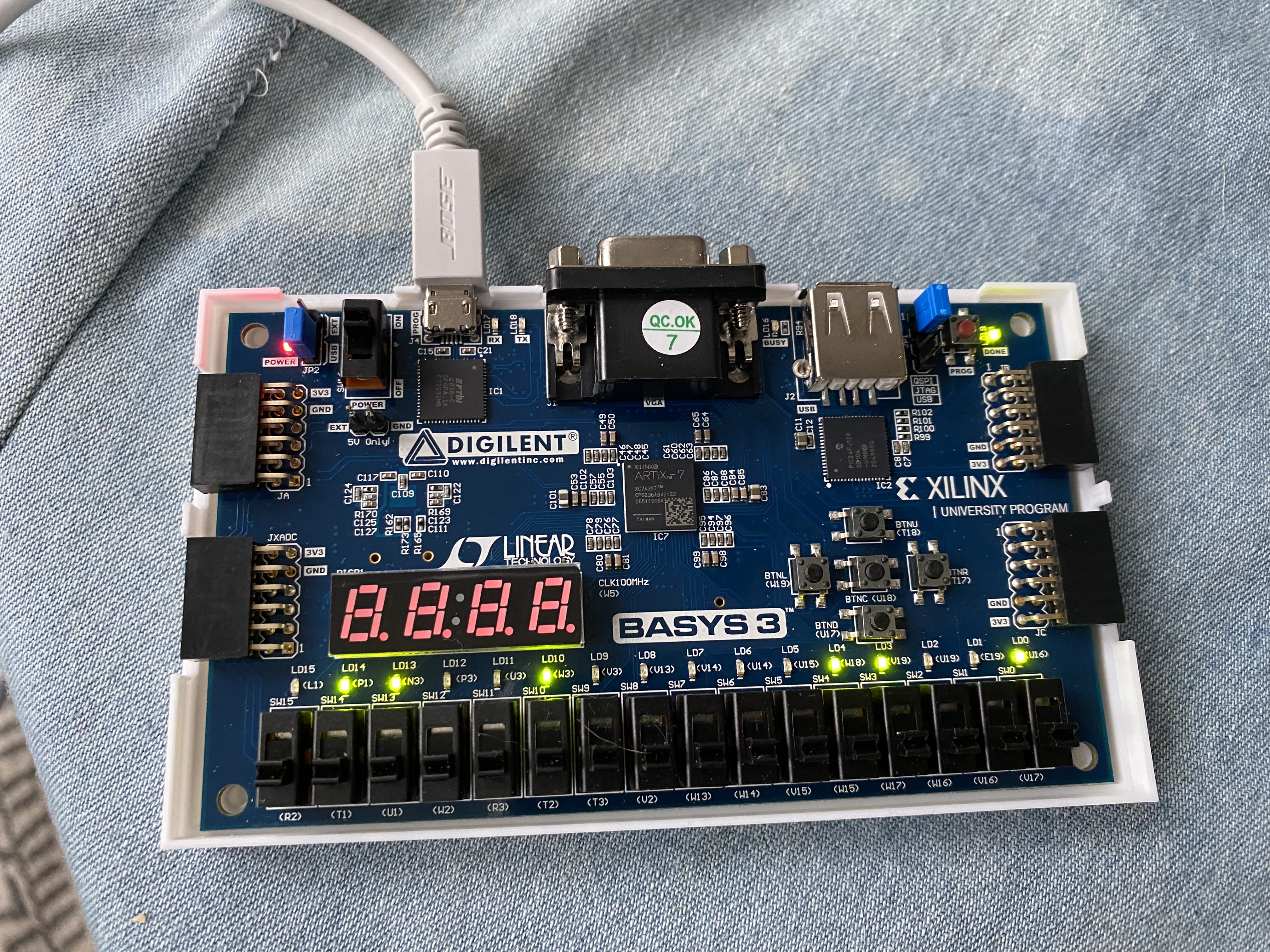
First I added the instruction and data memory to the SoC module and when I got it to compile, I got an error that nothing was produced. This turned out to be because I didn’t have any outputs, the optimizer was able to remove every component resulting in an empty implementation. The easiest way past this was to connect a couple of things to the LEDs on the board, this way I could see the same results as the test in the testbench program, namely that the program ends with DataAdr == 100 and WriteData == 25.
This causes Vivado to actually generate some circuits, however it then complains it can’t find a layout that works at 100MHz. The solution is given in Bruno’s book to include a clock module from the IP section of Vivado. This clock module is free, easily downloaded and incorporated into your project. With this you can configure the clock to a slower speed to allow more to happen in one clock cycle. Configuring the clock to 50MHz allowed Vivado to produce a layout and then generate a bitstream that I could download to the Basys board. This then lit up the LEDs as expected. The source code for the SoC module is at the end of this article.
Where to Next
There is still a long way to go to create a general purpose computer. The Assembly Language program is hard coded into the circuitry of the FPGA. There is very little I/O with only using a switch for reset and then the LEDs to give a limited view of the address bus.
Further the Vivado optimizer can remove a lot of circuitry because not all 32-bits are used in this example and it can execute the program in the optimizer and hard code the result. To start to make this useful it would be nice to:
- Add memory mapped I/O for more devices on the Basys board. Such as outputting numbers to the four seven-segment displays.
- Add more instructions from the RISC-V instruction set.
- Provide a way to download the machine code Assembly Language to the processor as it’s running. I.e. hard code a boot loader rather than the actual program.
- Add support for a VGA monitor, as the Basys does have a VGA video port. Similarly figure out a way to connect a keyboard.
The Basys 3 has rather limited memory, since it only has its distributed memory spread over various LUTs. More expensive boards from Digilent include banks of RAM that could be used to hold more extensive programs. I suspect if I wanted to port a BASIC interpreter, I would need the next Digilent board up in the line. But I have a lot of work to do before getting to that point.
Summary
Creating a small CPU on an FPGA is certainly fun, but it shows the amount of work required to create a CPU and its ecosystem. This is a simple CPU with a few instructions, no pipeline and no caches. But at least it is 32-bit. Implementing some of the RISC-V instruction set, which means I can use the GCC Assembler running on a Raspberry Pi to create the machine code. It is a long way from having what is required to run the Linux Kernel. But for those interested in minimalistic computing this is another alternative to creating custom CPUs that is a bit easier than constructing one out of discrete TTL logic components.
`timescale 1ns/10ps
module soc(
    input wire                         clk,
    input wire                         reset,
    output logic [15:0]    led
);
    logic [31:0] WriteData, DataAdr;
    logic MemWrite;
    logic [31:0] PC, Instr, ReadData;
logic clk_50;
generate
   sys_pll u_sys_pll
    (
     .clk_in1  (clk),
     .clk_out1 (clk_50)
     );
endgenerate
// instantiate processor and memories
    riscvsingle rvsingle( clk_50, reset, PC, Instr, MemWrite,
        DataAdr, WriteData, ReadData);
    socimem imem(PC, Instr);
    socdmem dmem(clk_50, MemWrite, DataAdr, WriteData, ReadData);
   always @(negedge clk)
    begin
        if(MemWrite) begin
            led[7:0] = WriteData[7:0];
            led[15:8] = DataAdr[7:0];
        end
    end
endmodule
module socimem(input logic [31:0] a,
    output logic [31:0] rd);
    logic [31:0] RAM[63:0];
    initial
    begin
    RAM[0]  = 32'h00500113;
    RAM[1]  = 32'h00C00193;
    RAM[2]  = 32'hFF718393;
    RAM[3]  = 32'h0023E233;
    RAM[4]  = 32'h0041F2B3;
    RAM[5]  = 32'h004282B3
    RAM[6]  = 32'h02728863;
    RAM[7]  = 32'h0041A233;
    RAM[8]  = 32'h00020463;
    RAM[9]  = 32'h00000293;
    RAM[10]  = 32'h0023A233;
    RAM[11]  = 32'h005203B3;
    RAM[12]  = 32'h402383B3;
    RAM[13]  = 32'h0471AA23;
    RAM[14]  = 32'h06002103;
    RAM[15]  = 32'h005104B3;
    RAM[16]  = 32'h008001EF;
    RAM[17]  = 32'h00100113;
    RAM[18]  = 32'h00910133;
    RAM[19]  = 32'h0221A023;
    RAM[20]  = 32'h00210063;
    end
    assign rd = RAM[a[31:2]]; // word aligned
endmodule
module socdmem(input logic clk, we,
    input logic [31:0] a, wd,
    output logic [31:0] rd);
    logic [31:0] RAM[63:0];
    assign rd = RAM[a[31:2]]; // word aligned
    always_ff @(posedge clk)
        if (we) RAM[a[31:2]] <= wd;
endmodule
Introduction to FPGAs
Introduction
Field Programmable Gate Arrays (FPGAs) are a form of programmable hardware that has become inexpensive and accessible recently. I recently purchased a Digilent Basys 3 FPGA development board for $200 based on a Xilinx Artix-7 FPGA. Xilinx makes their development software available free for non-commercial use on these lower end chips. If you’ve ever been interested in how chips are designed and developed, then FPGAs are a great way to get started. You program FPGAs using the same hardware design software that is used to design custom integrated circuit chips (ASICs). In this post, we’ll start to look at what an FPGA is and how it works.

Logic Gates and Truth Tables
Anyone that has taken a basic logic course will have encountered truth tables for the basic logic operations. Below are the basic logic building blocks including their symbol and truth table.

You can then build complicated logic circuits out of these building blocks. If you want to build an I/C, then you use a design pattern of the transistors for each logic gate. For instance a possible AND gate made out of transistors and resistors is below.

To build a CPU, you need a few more elements than basic logic gates, namely memory and a way to synchronize everything to a clock, but this is a good starting point.
FPGAs
The basic idea behind an FPGA is to provide an array of circuit elements that can execute any truth table, or lookup table in FPGA parlance. You program the FPGA by downloading all the truth tables to it and then execute them. A Xilinx Artix-7 FPGA contains thousands of configurable logic blocks (CLBs), each of which can be configured to execute a single 6-input lookup table (LUT) or two 5-input LUTs.
When you start building arithmetic operations from basic logic elements, you need a carry output as well. The CLBs support carry out operations so you can implement circuits like full adders. Further some of the CLBs contain memory and shift registers that you can use.
Extras
As chip densities and transistor counts increase, FPGA can have quite a large number of CLBs on a single chip. Further other elements are added to optimize common operations. For instance performing multiplication using the tools described is possible, but quite slow. Most FPGAs now contain custom multipliers that can be configured in or even a DSP. Similarly most FPGAs have custom components for external interfaces such as USB or I2C.
Programming
FPGAs are programmed using hardware description languages such as SystemVerilog or VHDL. Both of these compile to what is required for your development board. The cool thing is that this same HDL could be used to generate the layout/masking for a custom application specific I/C (ASIC). The Xilinix development environment is Vivado which supports writing and compiling your HDL along with creating testbenches and running simulations. It also has limited debug support for running on your development board. Here is the source code view:

Here is the generated circuit diagram:

Here we run a simulation and can study the timing diagram:

The thing to remember is that HDL describes hardware and even though it looks like a programming language, it only superficially behaves like a programming language.
Why FPGAs?
FPGAs typically run at 300MHz or so. This is well below the speed of typical ARM, Intel or AMD CPUs. The big advantage of FPGAs is getting something up and running quickly using an iterative development/debug cycle. If you are creating ASICs then you need to do the design, send them out for test manufacturing and then test what you get back, a slow and expensive process.
For instance, a lot of the first RISC-V CPUs on the market were implemented on FPGAs. This is why they usually have fewer CPU cores and run at around 300MHz. This brought them to market quickly to let people start writing RISC-V code, such as adding basic support for RISC-V in the GCC compiler and the Linux kernel.
Another advantage of FPGAs is that if there is a bug, you can reprogram them. FPGAs are commonly used in automobiles and this allows the manufacturers to change the hardware via software updates rather than executing a costly recall and having to replace ASICs or circuit boards.
The other thing to note when implementing in hardware, like with FPGAs, is that you have a much greater freedom to run things in parallel. In fact everything runs at once by default, and you have to do some work to synchronize or serialize operations. This allows you to develop highly parallel processes, like for GPUs or TPUs. This level of parallelism gives FPGA development a huge advantage over CPUs and traditional programming, for certain application areas.
Summary
If you are interested in how I/Cs or CPUs are designed and implemented then inexpensive FPGA boards from companies like Digilent are a great starting point. The cost of entry is minimal and even if the hardware is lower end by today’s standards, it still gives you a long runway for learning. A great diversion for DIY electronics hobbyists.
Battling US Export Controls
Introduction
My electronics DIY hobby must be getting more advanced as I’ve started running into trouble with US export controls designed to keep advanced US technology from terrorist states and others the US doesn’t like. I was having another look at RISC-V processors and how they are progressing, as part of this there is a lot of information on how to design a RISC-V CPU. Modern chips are mostly designed using hardware description languages (HDL) such as SystemVerilog. I’m not going to design a custom chip and certainly can’t afford to get one manufactured; but, this led me to Field Programmable Gate Array (FPGA) chips that let you run your HDL scripts through hardware configuration. Many of the early RISC-V CPUs were only produced on FPGAs and these days there is a lot of interest in FPGAs producing things like retro-CPUs, AI accelerators, robotic controllers and custom GPUs. The cool thing is that the software behind all this is free for student and non-commercial use; but, there is a catch.
Siemens SystemVerilog
I recently read the excellent book: “Digital Design and Computer Architecture, RISC-V Edition” by Sarah Harris and David Harris. To do the labs and exercises in the book required using the ModelSim student edition, now owned by Siemens. I went to download this and received:

I didn’t pursue this and was just sad I couldn’t play with the labs in the simulator.
Xilinx Vivado
This got me interested in FPGA design and I am currently reading “FPGA Programming for Beginners” by Frank Bruno. This book recommended using a Digilent development board for Xilinx Artix-7 FPGAs. The boards are easily available to purchase, including on Amazon. However, after my previous experience I thought I better check out the software first and sure enough ran into US export regulations again.

Xilinx was purchased by AMD in 2020 for 35 billion. Xilinx is the largest manufacturer of FPGA chips and their software and tools are excellent. There is an automated way to get approval, but it requires you to have an email address from an approved company or educational institution. I have neither and wondered if I would be able to get through the bureaucracy of such a large company to get approval.
I pressed the button to send an email explaining why the automated approval wouldn’t work for me. I explained my situation and pressed send. I had pretty low expectations and started looking at open source alternatives for FPGA development. I was pleasantly surprised to receive an email in about an hour asking for some government ID. I emailed back a photo of my drivers license and was given download permission in another hour. I was then able to download the software and get up and running. I then ordered the development board for under $200 from Amazon and it arrived in under a week.
Why All This Hassle?
So why is the US restricting people from FPGAs? Why restrict the student development boards? Why not just restrict the higher end products? I think the assumption is that Iran, Russia or North Korea would be able to create FPGAs to accelerate the computations required in their drones and missiles. This could be true, however the various CPUs from Intel, AMD and ARM that you can buy off the shelf are pretty powerful. The restrictions seem the tightest on software, but then downloading software is a direct export to other countries. When I bought my Digilent FPGA development board, I ordered it from Amazon.ca and had it shipped to B.C. It was fulfilled and shipped from Montreal. I imagine that if my shipping address was in Iran, Russia or North Korea that the order would have been canceled.
I’m not too sure how effective this all is, as I imagine members of these countries can use VPNs to spoof outside locations and produce fairly convincing fake IDs to fool whoever is checking these things. For the physical hardware, I wonder how easy it is to ship it to a third country that doesn’t have strict export restrictions and then ship it from there. For instance shipping the hardware to China, where it is probably manufactured anyway, and then shipped to, say Russia or North Korea.
Placing roadblocks and not providing any support probably slows down development, but doesn’t stop it. There are also a number of open source projects looking to open source the entire FPGA tool chain. Once these mature, I don’t think export restrictions will work on the software, at least in this space.
Summary
I feel the US export restrictions are doing more to limit students learning about advanced technology than they are keeping advanced technology away from rogue states. If the US doesn’t do more to promote technology education, they are going to keep slipping from their position as a technology leader in the world. After all, the technology innovations for the future are going to come from countries with the best educated students. The US runs the risk of putting too many roadblocks in the way of learners and hence restricting future technological advances.
KiCad on the Raspberry Pi
Introduction
The Raspberry Pi has heralded in a renaissance in DIY electronics. The GPIO ports open up a world for custom electronics projects of everything from home control systems to fully autonomous robots. Most projects involve connecting a number of discrete components together on a breadboard and then connecting a few leads over to the Raspberry Pi’s GPIO ports. KiCad lets you take these projects to the next level allowing you to design and manufacture custom printed circuit boards to replace the breadboard with something more permanent. KiCad is an open source design tool that lets you nicely layout your electronic circuits, produce schematics and then take these and produce a PCB. Commercial PCB software is expensive and KiCad, now at version 6, has progressed to compete with the best of these.
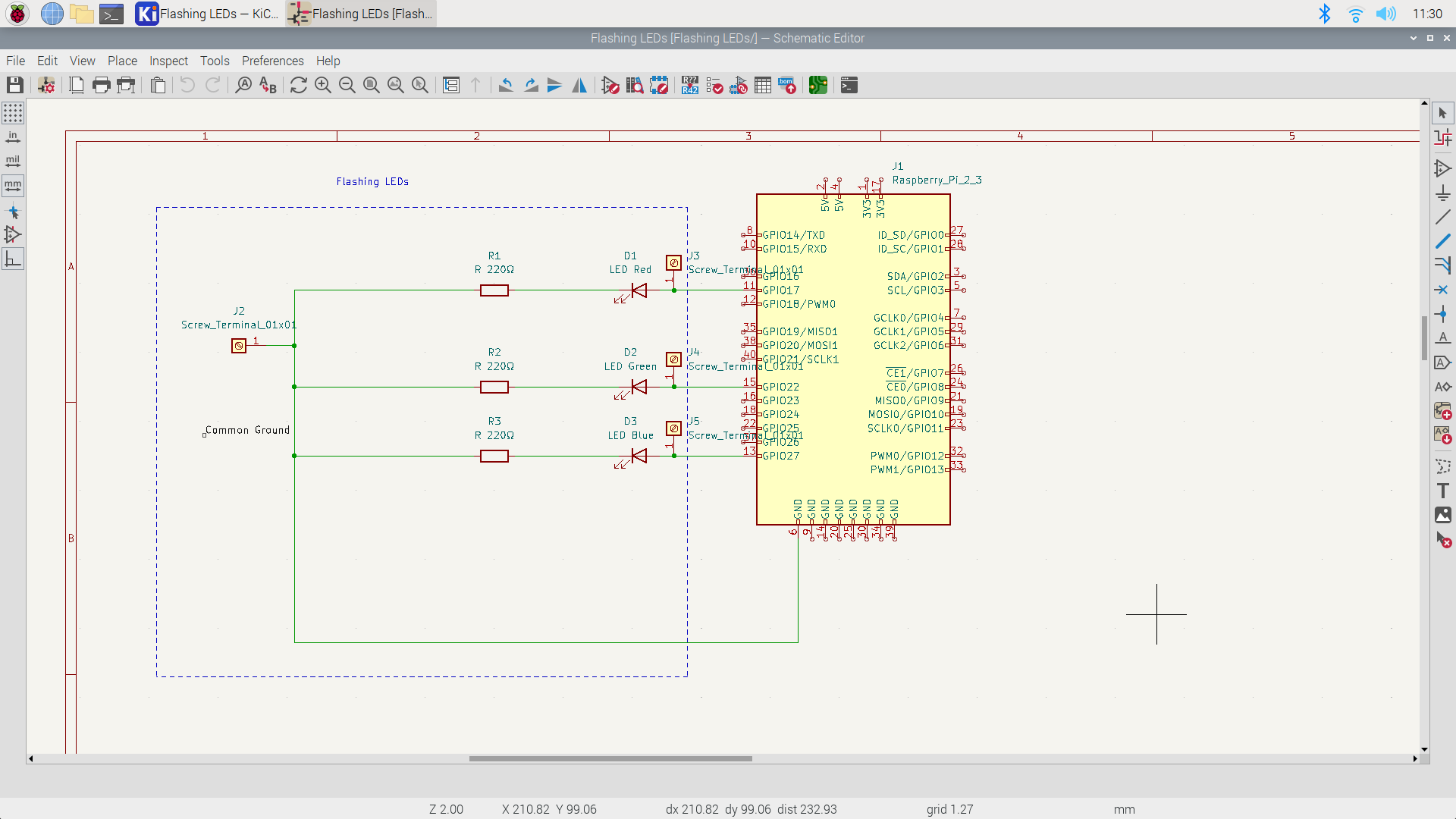
In this article, we’ll look at using KiCad to design the circuit for the simple flashing LED hardware that we’ve used in so many previous blog articles.
Designing the Schematic
Creating a schematic is fairly simple in the Eeschema tool. The only gotcha was that the first time you run it, some operations are so slow you don’t know what’s going on. For instance, I was stuck on how to add my first symbol, but that’s because it was building the symbol library and on a Raspberry Pi, this takes a while. Once I was past this, everything went quite smoothly and I was impressed as to how easy this CAD program is to use. The general procedure to building a schematic is to:
- Add all the symbols to the schematic.
- Arrange the symbols to make wiring them simple, possibly rotating them.
- Add the wires to connect everything.
- Add documentation, such as proper labels and comments.
I added a Raspberry Pi GPIO header to the diagram to document how to wire up the flashing LEDs to a Raspberry Pi. In the properties for this symbol, I marked it as not going on the PCB board and not to be added to the bill of materials. I added terminals by each lead that goes to the Raspberry Pi, so if I create a PCB board then wires can be soldered to these and connected to the Pi’s GPIO pins. If I was only producing documentation, I could have left these terminals out.
If you are going to generate a PCB board then you need to ensure that each component has a footprint associated with it, which gives the precise measurements for the size and placement of pads on the board that is created.
Producing the PCB
Once you have the schematic, if you want a PCB, then there is a tool that generates the PCB from the schematic. This creates a board with all the components. You then need to:
- Arrange the components how you want them (just a matter of moving them).
- Provide the circuit paths. Usually following the wires from the schematic as a guide. You can place these on the front or back of the board, for my simple board, I placed them all on the back.
- View the finished board to ensure it is what you want.

I found the creation of the PCB to be quite painless. Of course with more complicated wiring, it can be more of a challenge and might require multiple PCB layers.
Now you can generate the Gerber files and send them to a service to manufacture the board for you.
Below are 3D renderings of the top and bottom of the board.


Summary
Too bad I didn’t know about this tool when I wrote my three books on ARM Assembly Language Programming. I would have produced much better documentation on the hardware projects in the books. Oh well, either next book or future editions.
I’ve struggled with using CAD programs in the past, but this one I found quite easy to learn and use. It runs on Windows, MacOS and Linux including the Raspberry Pi. I have a nice large monitor connected to my Pi and found it worked quite well as a CAD workstation.
I was surprised with how easy it is to design PCB boards with KiCad and can see how this is a great contributor to the surge in DIY electronics.
